Journal of Machine Intelligence and Data Science (JMIDS)

Volume 6 - Year 2025 - Pages 39-49
DOI: 10.11159/jmids.2025.004
In-situ Repair of the Stator Core of Hydro-generator Establishing the Process
Pankaj Gupta1, Netrapal Singh2
1NHPC Limited
Sector-33, Faridabad - 121003, Haryana, India
pankajgupta@nhpc.nic.in
2NHPC Limited
Sector-33, Faridabad - 121003, Haryana, India
netrapalsingh@nhpc.nic.in
Abstract - Faults on generator windings are more common, but many times core is also affected. The suppliers of the equipment do not guarantee satisfactory in-situ repairs of the stator core. They recommend partial or complete replacement of the core. For localized damages it may not make sense to go for entire core build up. So, the owners frequently attempt temporary solution and in-situ repairs. But the methodology of localized repair is always random. Developing efficient process for localized repairs on stator cores is essential so as to reduce the cost and outage time of the machines as well as for ensuring trouble free post repair operation. The present case study emanates from the experience gained from the field repairs of core of the stator of a hydro-generator in India. This study presents a case where the actual damage to winding insulation has been caused by deteriorated stator core laminations. The case study describes the probable causes of deterioration of winding and core, methods of locating the fault, the process adopted during the repairs and the benefits derived from the in-situ repair of core. Through the repair process, a methodology has been established for undertaking such localized repairs in stator cores.
Keywords: In-situ repair, Stator core, Hydro-generator.
© Copyright 2025 Authors - This is an Open Access article published under the Creative Commons Attribution License terms (http://creativecommons.org/licenses/by/3.0).
Date Received: 2024-01-11
Date Revised: 2024-09-10
Date Accepted: 2024-12-20
Date Published: 2025-03-04
1. Introduction
Of all the components of a hydroelectric generating unit, generator is the most likely component to fail. The coils and bars in a generator have a finite life. Over a period of operation, their insulation deteriorates due to the combined stresses of operation, and they may breakdown at a point of time, which is also the moment at which the winding must be replaced. However, breakdowns in generators are not always the result of normal ageing process. As such, repair and replacements are not always planned.
Faults and subsequent breakdown in generators are not restricted to winding only and may cause damage to stator core also. Whereas faults in windings can be attended by replacement of the affected portions, repairs on a stator core of a hydro-generator can be challenging and require timely decision on the repair process to be adopted.
The conventional processes for repair of damaged stator core may require replacing the stator core (and winding) and thus need longer outages besides the higher costs involved. But this can make sense only if there is extensive damage which has affected the core and/or winding. For attending localized damages, the owners of the generating units facing such breakdowns frequently go for the temporary solutions until a permanent replacement/repair is performed as per the life cycle renewal of the units. Developing efficient repair methods for stator core for reducing the cost and outage time of the machine is essential for handling such situations.
2. Stator construction
2.1 Stator Core
A stator core in a large hydro-generator is constructed from thin laminated sheets of electrical grade steel so as to limit eddy current losses during operation. Each lamination is insulated and the stator core laminations are grounded, ensuring that circulating currents as a result of the induced magnetic flux do not occur, thus avoiding localized current flow and overheating of the laminations. The slots formed in the stator core hold the stator winding.
2.2 Stator Winding
Stator winding in large hydro-generators is made up of bars formed out of large number of insulated rectangular copper conductors of small sections interposed in slot portion to reduce eddy and circulating currents. The bars are coated with semi-conducting varnish to avoid corona and flash over. The over-hang part is tied with bandage rings after placing insulating spacers between them.
3. Fault on Stator Core – Why do They Occur?
Poor quality of material, unsatisfactory installation and premature aging due to thermal/mechanical/electrical stresses during generator operation may cause stator core and windings to fail even before their estimated life. Many times, environmental factors also contribute towards deterioration of stator and subsequent failure.
3.1 Failure of Stator Winding
A winding failure is often the result of gradual deterioration of the insulation system followed by an event, such as an external fault or voltage surge that stresses the already weakened insulation beyond its reduced capability. A number of processes can produce deterioration. These include:
3.1.1. Thermal Factor
Thermal deterioration occurs when insulation is heated beyond its design temperature. This causes the breakdown of chemical bonds in the insulation material. This, in turn, makes the insulation brittle and increases the possibility of cracking. Overheating of the insulation can be caused by overloading or by a cooling system failure.
3.1.2. Electrical Factors
Electrical deterioration results from partial or slot discharges. Partial discharge refers to the arcing that occurs within small voids in the insulation. Often these voids are pre-existing defects created during the construction of the winding. The arcing causes a decomposition of the insulation on the interior surface of the void, gradually causing the void to grow and weakening the insulation over time. Partial discharge can also occur in the end windings. This can happen when inadequate clearances create voltage gradients that exceed the breakdown strength of the insulation. A slot discharge is similar to a partial discharge. Slot discharges can occur in generators that are subjected to high thermal cycling (heating and cooling due to rapid load changes or frequent starting and stopping). When high thermal cycling occurs in generators with long stators, the differing thermal expansion coefficients of the various components (conductor, insulation, and core) produce shear forces. These forces result in the separation of the ground wall insulation from the stator core, producing a void. The voltage at the surface of the insulation where the void occurs rises to the phase-to-ground value. This results in an arc, which breaks down the insulation at the surface, eventually causing the insulation to fail.
3.1.3. Mechanical Factors:
Mechanical deterioration occurs when excessive movement or vibration leads to insulation wear or cracking. Within the stator slot, loose coils or bars can occur due to insulation shrinkage or poor construction. Magnetic forces at twice the line frequency cause the bars to vibrate, which can cause the insulation to wear and/or separate from the stator core. As with the case of thermal cycling, separation of the ground wall insulation from the core results in a slot discharge. In the end winding, inadequate bracing can lead to excessive vibration. The bracing may also loosen due to the high transient torque produced by an out-of-phase synchronization event or a close-in fault. The impact of repeated events is cumulative. Excessive vibration leads to wearing or cracking of the insulation.
3.1.4. Environmental Factors
Contamination is the penetration of water, oil, or dust (coal, brush gear sediment, and so on) into the insulation. Contamination degrades the insulation in two ways. First, it causes a reduction in the electrical or mechanical strength of the insulation. Secondly, contamination provides a medium for surface tracking, primarily in the end winding. Surface contamination creates a path for small capacitive currents driven by potential differences within a phase or between phases. These currents lead to surface discharge in the air adjacent to the surface and the formation of carbon tracking. The low-impedance paths formed by these tracks can lead to a fault.
Interactions between the different deterioration processes described can accelerate the deterioration of the winding. For example, insulation that has become more brittle due to thermal degradation is more susceptible to mechanical effects.
3.2. Failure of Stator Core
Although the stator core is one of the most reliable parts of a rotating machine, the original design, materials, and installation quality may influence its rate of aging. Stator Core can get damaged due to Slot Discharge Activity, Intense Partial Discharge Activity in the slots, high inter-laminar voltages from system upset breaking through inter-laminar insulation, Inter-laminar shorts from transients and winding faults, Over-fluxing, Burning of core near coils from winding failures.
Core also gets deteriorated by various factors, which particularly affect its lamination insulation. These factors are:
3.2.1. Thermal factors
The degradation of core insulation can be due to general or local overheating. Loss of cooling, and partial or complete blockage of ventilation ducts can be the factors. Local/general overheating may occur be due to general loss of cooling or due blockage of radial or axial cooling passages in the core. Thermal aging causes migration of carbon to the grain boundaries thus resulting in magnetic aging.
3.2.2. Electrical Factors
Degradation of stator core can be caused by operation of the core outside of its design parameters or stator winding failure. Under-excitation and over-excitation can result in high core temperatures in two different areas: the step iron and back of the core, respectively. The step iron at the two ends of the core is the most stressed part of the core. Failure of inter-laminar insulation can lead to complete core meltdown. This situation can occur during the synchronization of generator with the system, if rotational speed and excitation voltage are not properly controlled. The loss of insulation on the stator core through‐bolts (some core designs) and stator winding earth faults in core slots or at core edges, can cause melting of the core iron, requiring partial or complete core replacement.
3.2.3. Environmental Factors
Contamination, e.g., by water condensation and corrosion, oil vapours, dust from brakes etc., attack inter-laminar insulation in the core. Element contamination and higher carbon alloys aging cause reduced magnetic properties.
3.2.4. Mechanical Factors
Vibration (or relative movement) in core can occur due to loss of core pressure (caused by settling of laminations), loss of insulation volume, collapsing of vent supports, improper assembly, core wave, excessive core temperature (and therefore possible buckling and even meltdown), failed clamping components, and other design-specific issues.
Movement between laminations may occur even due to large differences in temperature between one part of the core and another, high machine vibrations, high forces observed during abnormal operation or system disturbance, or loss of core-to-frame attachment. When laminations move relative to each other, insulation is abraded and this may quickly lead to shorts and core or winding failure of a catastrophic nature. The movement can allow for flexing of the laminations and the electrical steel can undergo cyclic fatigue and become brittle, crack and break. The lamination edge can move out of position and impact the windings resulting in insulation damage.
4. Protecting the Stator Core – Minimize Damage
The damage to generator winding and core during fault events can be minimized if the machines are adequately protected. Protection can take many forms, mechanical and electrical. Any core damage is likely to result from a winding failure. While a number of winding protections are deployed, stator cores are indirectly protected by the stator winding protection systems that may be installed on any particular machine, and to some extent the bearing temperature, air gap and vibration-monitoring equipment. For simple ground faults the extent of the damage is limited by the protection scheme in use which will also be affected by the method by which the machine is grounded. The most direct core protection is Volts/Hertz, protecting the core from over-fluxing, particularly during off-line runs before synchronization or during off line tests.
5. Locating the Stator Core Faults
Given the bigger sizes of stator and less accessibility of the core and winding areas in a hydro-generator, locating the point of fault is a time taking activity. Minimum dismantling during the process helps in fast restoration and lesser downtimes.
Several methods are used to locate the ground faults in stator winding. These include megger of the individual phases and parallel paths, injecting and following current in the affected phase, ‘Smoke Test’, ‘Non-destructive’ methods involving use of low-power DC source to charge the winding and tracing discharging transient currents.
After identification of the location of winding fault, and removal of faulty section, stator core should be inspected. A visual inspection depending upon physical access to the core and winding is the first step. Removal of two to four rotor poles can facilitate access to the stator bore surface. Depending on the type of damage (deep-seated damage after a short circuit or significant damage on the core air gap surface), it might also be required to remove the rotor before an inspection, however, the removal is generally avoided to the extent possible as it involves work on various other components and corresponding expenses on manpower and material as well as loss of time.
The inspection should include the stator connections (group, serial and circuit ring connections), winding circular, phase and neutral busses, bracing elements (ties, bracing ring, etc.) and wedging system. The inspection should also include the ventilation ducts, bore and back surface of the core to help identify in-slot damages. Looseness in the laminations should be checked by visual and knife penetration inspection. Similarly, condition of step laminations be ascertained. An ELCID test is highly recommended. A loop test or core magnetization test may be performed to detect hot spots in the core.
6 . Damage assessment and decision making
The repair work on stator core can be time consuming and a costly affair. The decision on the restoration process to be adopted always needs to be dealt on merit of the case. Partial or full Replacement of core may be required. Owners also go for complete replacement when the components are at the end of their useful life and/or design improvements are necessary.
When the core inter-laminar insulation has aged or been mechanically abraded to the point where unacceptable core heating is occurring or will become probable in the near future, or when there is core damage from inter-laminar shorts, or when the mechanical properties of the laminations become brittle to the point where slot wedging or core attachment breaks down, a replacement of core should be considered. Alternatively, partial replacement of the affected area of core and winding can be undertaken when other areas are only slightly affected and may not need significant repairs.
However, there are incidences when only a few laminations and a small area is affected. Going for costly replacements in such cases does not sound to be a good decision. But the decision to go for localized in situ repairs is not easy as well, considering the absence of a defined and established repair process.
7. In-situ repairs on stator core – A case study
Whenever a fault occurs in generator and damage is detected and located in the stator core, a logical decision on repairs is the first step towards restoration. Very often, the suppliers of the equipment do not guarantee satisfactory repair (and post repair performance) and suggest a partial or complete replacement of the stator core (and winding). However, considering the replacement time and cost of a stator repair, it is often advisable to attempt an in-situ localized repair even if the unit will not be operated near full rating and a core in less than perfect condition suffices subject to satisfactory operating parameters. But in absence of a defined process for in-situ repair, lack of support/recommendations from original equipment suppliers, uncertainty of performance post repairs, make the decision making rather tricky and difficult.
Similar situation was faced when fault occurred on a 180MW hydro-generator. The repairs were carried out without core disassembly and replacement. Finally, a repair process was formulated to facilitate such in-situ repairs with more confidence and ease.
7.1. Generator Details
Ratings: 200 MVA, 13.8 kV, 0.9 PF, 3 Phase, 50 Hz
Stator Current: 8367 at 200 MVA
Rotor Current: 1133 Amp at 285 Volts
Number of Parallel Paths: 4, Y Connected
Number of Slots: 336
Number of Rotor Poles: 28
Insulation: Class-F
Make: General Electric, Canada
Owner: NHPC Limited, India
7.2. Occurrence of Fault
On 30.08.2019, Unit No.-3 of the power station tripped on stator earth fault. From the disturbance recorder, it was observed that voltage in Y-Phase dipped from 8.0 kV to approx. 3.5 kV, with no substantial increase in phase current, indicating an earth fault in Y-Phase. The phase voltages and currents in R-Phase and B-Phase were found to be normal. Insulation Resistance (IR) of Y1 path was found zero.
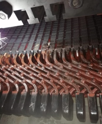
7.3. Identification of Fault Location
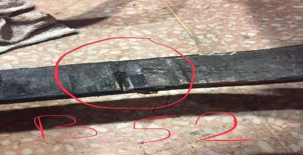
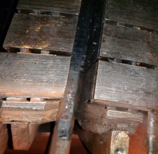
Visual inspection of winding and core shown some flashover in lower area of the winding near Slot No.-51 (Fig. 1 and Fig. 2). Winding Bars in Slot no-51 segregated and IR was tested on them. Results were satisfactory. Further sectionalization of winding in faulty path (Y1) was carried and IR tests carried out.
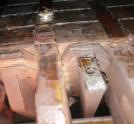
IR of a section of winding covering around 25 slots found zero. To avoid further sectionalization, controlled DC current, up to 60-70 amperes, was injected in the faulty section of winding using a welding machine. Minor spark was observed in slot-52. Bars in the slot were segregated. IR of bottom bar in slot-52 was found to be zero (Fig. 3).
7.4. Inspection and Evaluation
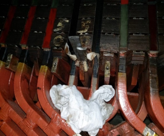
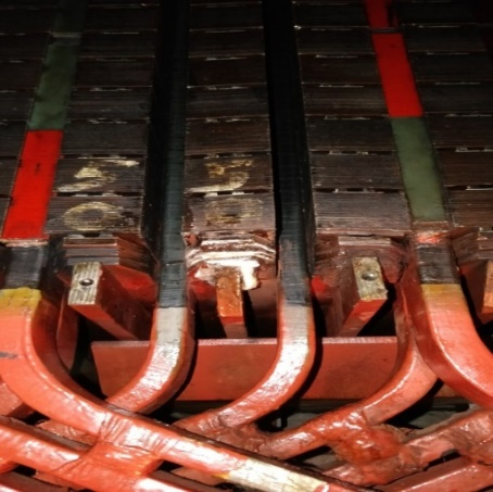
During inspection of the area around the seat of fault it was observed that the step laminations and finger of slots 50, 51 and 52 in the lower end area of stator core were found damaged due to heating. lamination packets between slots 50, 51 and 52 were found disturbed/loosened (Fig. 4). Two number air ducts just above the packet of loosened laminations were found blocked.
During inspection of overhang portion of winding, partial discharge points evident in the form of black spot formation in air gap between top and bottom bars just after exit from the stator core slots were observed.
7.5. Fault Assessment and Decision
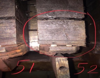
Earlier, it appeared that the fault was restricted to winding only. However, after taking out the faulty bar (bottom bar in slot 52), it was observed that the outer visible edges of step laminations of the stator core, between slot 50 and 51, and slot 51 and 52, at the lower end of the stator core had got heated up.
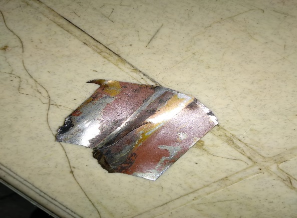
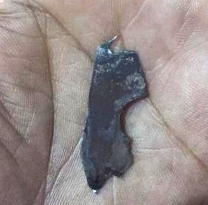
Outer edges of about 15 laminations in lower most portion had vaporized completely while partially burnt-out edges of about 25 laminations were in place. A piece, measuring 50 x 50 mm (Fig. 5), of one such lamination between Slot-51 and 52 had got torn from the remaining lamination and moved from its place by about 2-3 mm. Upon inspection of the punctured bottom bar, a cut-groove about 25mm in length, 2-3 mm in width and 2-3 mm in depth was observed (Fig. 6). The position of the groove was corresponding to the displaced piece of step lamination. Thus, it was concluded that the displaced piece of step lamination had gradually cut into the bottom bar in slot 52, thereby puncturing it and resulting in earth fault at the point of puncture.
7.6. Decision on Repair Process
The nature of damage was discussed with equipment suppliers who suggested a partial replacement of the core and ruled out possibility of an in-situ repair of minor nature. This would have resulted in excessive outage time and corresponding losses, as the power station was generating to full capacity at that point of time. So, as per field experience, the following repair process was devised and carried out:
- Removal of Bottom bars in slot 50 and 51
- Removal of remaining identified bars, to facilitate the repair work of core laminations.
- Removal of rotor poles
- Removal of stator hot air coolers for cleaning and inspection of back of the stator core
- Removal of burnt-out outer portions of the laminations
- Cleaning of area around and in between the laminations including the air ducts
- Insertion of core insulation varnish in between the laminations
- Preparation of nomax paper packing (nomax paper dipped in epoxy varnish)
- Insertion of above packing in between the laminations for providing tightness and insulation (Fig, 7).
- Preparation of packing (wool-felt dipped in epoxy vanish)
- Insertion of above packing in between the laminations for providing tightness and insulation (Fig, 8).
- Reopening of the air ducts blocked by debris.
- Checking/tightening of stator core bolts.
- Replacement of damaged winding bars in slot 52 (2 bars)
- Replacement of other bars (14 numbers, removed for replacement of the bottom bar in slot 52.
- Repair of damaged core
- Testing as per procedure.
- Cleaning of entire stator core air ducts and winding overhang.
- ELCID test of stator core carried out and found satisfactory.
- Application of core varnish and semiconductor paint and left for drying.
- Insertion and assembly of rotor poles carried out.
- Refitting of stator air coolers which were removed.
- Final inspections
- Final testing, cleaning.
7.7. Validity of the Repair Process Adopted
Any repair process which is otherwise undocumented earlier and has been carried out for saving time and cost generally cannot be recommended for all conditions before validation.
After a period of around one year (on 18-07-2020), a similar problem reappeared in another section of the stator. This time, the outer visible edges of step laminations in the lower end of the stator core (between slot 50 and 51) had got heated up, leading to vaporization of some laminations and loosening of step laminations between slot 50 and 51. Also, the packet of laminations just above step laminations had also loosened (Fig. 9). A piece, measuring 25 mm x 25 mm (Fig. 10) of one such laminations between Slot-50 and 51 had got torn from the remaining lamination and got displaced from its position by about 8 mm to 10 mm. This piece cut a groove of about 20 mm x 2 mm and 1-2 mm depth into the top bar in slot 51, thus puncturing and grounding the top bar.
Besides this damage, no damage or deterioration was observed in the laminations in adjacent slots repaired in the previous year. The fault was repaired in exactly the same manner and by adopting the same process as adopted in previous year.
7.8. Benefits of the Restoration Work
During both the occasions of breakdown, the fault had occurred during peak season. Thus, the restoration work was to be carried out within minimum possible time with satisfactory level of repair outcomes (Fig. 11) and post repair unit operation. The equipment manufacturer had indicated that a viable and immediate solution may not be possible since the fault was in lower areas of the stator core, thus calling for a rebuild of the entire core. If, as per recommendation of equipment supplier’s team, core build up was to be taken up, an expenditure of somewhere around INR 150 million ($ 1.8 million) would have incurred. This process would also have led to Plant Availability Factor loss and generation loss for at least 8 to 12 months. Since the fault was in a small portion of the stator core, it did not make sense to go for the entire core build up besides incurring huge losses on generation. Accordingly, contrary to the views of the equipment supplier, it was decided to take up the localized repair works. The first repair took 56 days. The repair time was significantly reduced to 13 days in the second repair, due to adoption of the process devised out during first repair. The direct savings on this account during both the incidences were substantial, due to reduced consultancy (from equipment supplier) and repair costs, and outage time saved by adopting the devised process. Further, considerable savings on account of generation loss were also made which cannot be precisely estimated, the power station being a reservoir scheme.
8. Fault Analysis and Discussion
Even though, the stator core is a more reliable parts of a rotating machine, it too deteriorates due to slot discharge activity, intense partial discharge in the slots, high inter-laminar voltages from system, inter-laminar shorts from transients and winding faults, over-fluxing, burning of core near coils from winding failures etc. Faults on windings may cause damage to core also.
The core insulation deteriorates due to general or local overheating caused by loss of cooling, and partial or complete blockage of ventilation ducts.
Failure of inter-laminar insulation can lead to complete core meltdown. This situation can occur during the synchronization of generator with the system, if rotational speed and excitation voltage are not properly controlled. The loss of insulation on the stator core through‐bolts (some core designs) and stator winding earth faults in core slots or at core edges, can cause melting of the core iron.
Thermal aging causes migration of carbon to the grain boundaries thus resulting in magnetic aging. Contamination, e.g., by water condensation and corrosion, oil vapors, dust from brakes etc., attack inter-laminar insulation in the core. Element contamination and higher carbon alloys aging cause reduced magnetic properties.
8.1. Core Temperature Distribution
Non-uniform core temperature distribution over the length and circumference, and temperature difference between the core and frame increases the risk of buckling of the core laminations and distortion of the air gap. During operation, it is important that core temperatures remain reasonably uniform over the length and circumference. For large hydro generators (core length greater than 2 m), the temperature difference between the core and frame is also a critical factor. The less variation there is in these values, the lower the risk of buckling of the core laminations and distortion of the air gap. The difference between the temperature at the top and the bottom of the core should be maintained within 5 degrees Celsius. The measurements for this are taken at the back of the core. Also, the temperature difference between the stator core and frame should be maintained within 20°C. Once again, the core temperature should be measured at the back.
Temperature variations around the circumference should be maintained within 10°C to avoid uneven expansion and contraction of the core and frame assembly. Limiting the temperature variations can ensure more uniform stator circularity and more even distribution of stresses on the sole plates and concrete.
For small to medium 5-50MVA hydro generators, the temperatures outlined above are less critical, but the operator should avoid excessive differences in these temperatures to ensure trouble-free operation of the core and frame assembly and the stator winding.
8.2. Interlaminar Movement
An important aging mechanism in a stator core is vibration or relative movement between laminations. This movement can be subsequent to loss of core pressure caused by settling of laminations, loss of insulation volume, collapsing of vent supports, improper assembly, core wave, excessive core temperature and therefore possible buckling and even meltdown, failed clamping components, and other design-specific issues.
8.2.1. Effect of Operating Conditions
Operation of the generators outside of their design parameters may lead to heating of the step laminations, causing them to melt. Under-excitation and over-excitation can result in high core temperatures in two different areas: the step iron and back of the core, respectively. The step iron at the two ends of the core is the most stressed part of the core. The laminations then loosen and start to vibrate or move relative to each other.
8.2.2. Effect of Non-uniform Temperatures
Movement between laminations may occur even due to large differences in temperature between one part of the core and another, high machine vibrations, high forces observed during abnormal operation or system disturbance, or loss of core-to-frame attachment.
8.2.3. Result of Interlaminar Movements
When laminations move relative to each other, insulation is abraded and this may quickly lead to shorts and core or winding failure of a catastrophic nature. The movement can allow for flexing of the laminations and the electrical steel can undergo cyclic fatigue and become brittle, crack and break. The lamination edge can move out of position and impact the windings resulting in insulation damage. Broken or displaced core clamping / vent fingers can result in lamination / winding degradation.
8.3. Established Cause of Stator Fault
Having discussed the probable causes that may lead to a fault on the stator, the condition and circumstances, including the machine operating parameters were revisited. It was observed that the power generated in the power station was being evacuated through two numbers long distance 400kV transmission lines. Due to the distance and the operating conditions of the lines their voltages generally remained on higher side. To control the line voltages, the generators were frequently operated in under-excited state, which led to heating up of the step laminations at core ends. This, coupled with clogging and obstruction of air vents provided in core near the hot spots, led to meltdown of the step laminations, thus causing further more vibrations in the laminations. Eventually, a piece of one of the laminations teared off from the lamination and punctured the winding bar, thus causing an earth fault on the generator. It was also observed that the gap between the top and bottom bars in a slot, just as they came out from the core area, was minimal, thus not allowing proper cleaning and cooling.
9. Establishing the repair process
Repair of faulty stator winding of hydro-generators, which involves the replacement of affected bars, is frequently adopted. However, when the faults are visible in core also, but are localized and minor (not justifying a complete replacement), in-situ repair of stator core can be taken up. Such repair is necessary to prevent additional heating that will gradually affect the winding and core, leading to a significant failure over time.
The process involves replacing the damaged area by an insulating material after removing the damaged area by cutting, sanding and straightening the laminations. A high capillary resin is then applied, and an insert (made of insulating material) is added to act as a cosmetic component, followed by an ELCID test to determine if a short between laminations is still there. Tightness checking of core bolts can be carried out. Gaps in between the loose laminations can be filled with thin, arrow-shaped epoxy glass laminate or epoxy glass wedges placed between loose laminations and bonded into position using air-drying epoxy resins. Such insertions should be evenly distributed over a span on laminations instead of using a single insertion of larger thickness. Care should be taken to ensure that the inserted packing do not work loose and get carried into the air gap, causing subsequent projectile damage elsewhere in the generator. If the damaged area covers numerous missing or severely damaged laminations, these areas of the core laminations can be ground away. Then the missing material can be filled with a nonmagnetic insulation laminate cut to replace the removed laminations.
It should be noted that repositioning migrated laminations may not always be possible, without causing potentially unseen damage elsewhere to the core. Shifting of the laminations within the winding slot can result in the thin sharp lamination edge causing damage to semi-conductive systems on the windings, and then cutting into stator bar insulation, hence resulting in winding failures. Shifting of the laminations can also restrict the cooling passages affecting localized core or winding cooling. Large diameter machines (hydro generators) can develop waves in the iron. In this case, restacking or partial restacking of the core may become unavoidable.
Post repairs, the affected area of stator core to be inspected periodically, including close monitoring of stator core and winding temperatures. Regular cleaning and testing of stator step laminations during maintenance activities need be carried out.
10. Conclusions
After a fault on stator winding and core, replacement of complete or partial winding and core may be the most safe and reliable repair which the equipment supplier may recommend. But considering the high cost and time involved, this approach is generally the last resort. Most owners generally go for the localized repairs but the methodology of localized repair is always random and variable from site to site and machine to machine.
Particularly, in case of core repair, the decision for going for localized repairs is as challenging as the repairs themselves. Skilled manpower, past history and deep understanding of the machine, and familiarity with the repair alternatives help to decide on the process to adopted and subsequent repair works.
Similar situation was faced in the above case experienced at a hydro power station in India, and after detailed evaluation, in-situ repairs of the core was carried out. The in-house repair works led to substantial direct savings. Further, in the process, a methodology is now established for taking up such repairs in future in other power stations facing similar faults in the generating units.
Disclaimer
The views expressed in the paper are the opinion of author and may or may not be that of the organization to which they are affiliated.
References
[1] Yang Yu, "Research on Diagnosis and Treatment of Abnormal Temperature Fault of Hydro-generator in Hydropower Station," IOP Conference Series: Earth and Environmental Science 768 012006, vol. 768, 2021. View Article
[2] R. Ward and A. Spisak, "Repair and Testing Guide for Generator Laminated Cores Grounded at the Core Outside Diameter," Electric Power Research Institute (EPRI), Palo Alto, CA: 2002. 1007441.
[3] Mallikarjunappa K, Chandrashekar D Keri, Vaidhyanathan V, Thirumurthy and Afzal Ahmed T R, "Diagnostic Testing of Hydro and Turbo Generators and Large AC Motors in Service," The Journal of CPRI, vol. 8, No. 3, pp. 171-184, September 2012.
[4] Mauro Uemori, Edson Leite Alves, Michel Spiridon (2020, July 30). Hydro Review Magazine [Online]. Available: View Article