Journal of Machine Intelligence and Data Science (JMIDS)

Volume 2 - Year 2021 - Pages 12-17
DOI: 10.11159/jmids.2021.002
Modelling and Analysis of a Serial Robotic Arm
Bin Wei1
1Algoma University, Department of Computer Science
1520 Queen St E, Sault Ste. Marie, ON P6A 2G4
bin.wei@algomau.ca
Abstract - The study discusses the design of a pick and place cylindrical robotic arm optimized for processes where parts will be moved from one assembly cell to another located above. A literature review was done to investigate the need for this type of design and the competing designs found in industry today. The kinematics, dynamics and control of the proposal robotic manipulator are studied, respectively. Future study will focus on building a prototype applying learning control to this robot to handle uncertainties that may occur in the industries.
Keywords: Modelling, Pick and Place, Robotic Manipulator, Control
© Copyright 2021 Authors - This is an Open Access article published under the Creative Commons Attribution License terms. Unrestricted use, distribution, and reproduction in any medium are permitted, provided the original work is properly cited.
Date Received:2020-11-22
Date Accepted: 2021-05-12
Date Published: 2021-05-19
1. Introduction
Manufacturers today are looking at any idea that can drive their costs down. Square footage on a factory floor is utilized with as much efficiency as possible. The possibility of urban manufacturing also drives the need for efficiency as rent in urban spaces can often be the largest contributor to overhead [1-2]. While cylindrical robotic manipulators have been around for a long time [3-4], they lack the range of motion at the end effector that this design will have. Robotic arms presented by companies like Fanuc or ABB offer a greater range of motion however that range of motion comes with the cost of increased footprint.
Automation has transformed the world of manufacturing and robotic arms are the first thing that comes to mind when people think of this revolution. By either replacing workers, or preforming tasks that otherwise could not be done, robotics arms have reduced costs and increased quality worldwide. Of these robots, pick and place are some of the most common. Pick and place robots can be positioned at the end of an assembly line cell to transfer a ‘part-in-progress’ to a new assembly cell conveyer. There are many other uses for robotic manipulators, but this paper will focus on the design for a new pick and place robot to be used in this application.
Fanuc, ABB, and Motoman are a few examples of companies that produce 5 or 6 DOF robots commonly seen in this role. This paper outlines the design of a new form of pick and place operation. Pick and place commonly refers to a robot grabbing a part, rotating about the Z axis (in the world frame) and placing the part down in a desired location. The new operation proposed in this paper is to vertically stack those assembly lines and design a robotic arm that is proficient at picking up a part, moving upwards along the Z axis (world frame) and placing the part down once reaching the new assembly cell. This type of operation would allow manufacturing plants to utilize space more effectively allowing for reduction in cost.
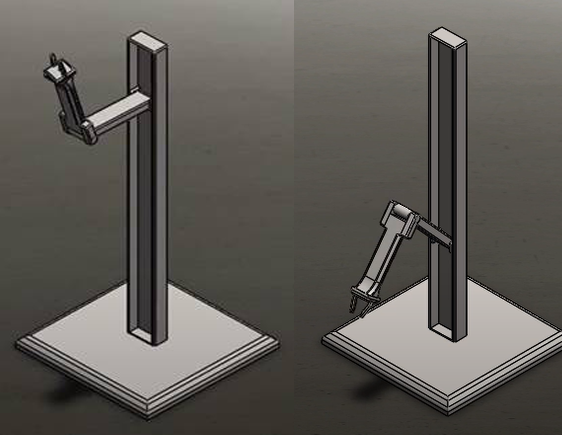
Figure 1 shows a picture of the design proposed in this paper. This paper is essentially an extension of the conference paper [5]. The prismatic joint in this design allows for the manipulator to be move up and down the Z axis (world frame) while maintaining a consistent footprint on the ground. It consists of four revolute joints and one prismatic. The prismatic joint can be modified for the robot to reach whatever heights is required. This paper will show the calculations for the kinematics, dynamics, and control systems as well as computer simulations.
2. Background
Researching alternate solutions into this problem yielded few results. The world of pick and place robots is broad and extensive, and the problem of limited space is not one that traditionally impacts manufacturing as it is often done in areas where real estate is inexpensive to drive down cost per square foot. In [6], it is stated that when purchasing space for manufacturing, companies are looking more broadly at the solution by emphasizing efficiency of space rather than location. Efficiency can take into account many different factors including distance to market, country, and utilization of space. In regard to utilization of space, the article also mentions that companies are building up instead of out. The price per square foot is the same whether the ceiling height is 24 feet or 32 feet. The article further mentions that the cost to optimize a current process or space is often less expensive than it is to buy a new one. These factors combine to show that the ability to build a manufacturing space upwards instead of outwards could be valuable to current day manufacturers.
While the ability to build up could impact current manufacturers when optimizing a process, it is also a strategy that could be utilized by manufacturers looking to put their manufacturing in a more visible space. In [7], the author talks about the growing world of small companies manufacturing in urban spaces. It is a growing trend that offers many advantages to traditional locations of manufacturing. In these small companies, rent cost per square foot is often one of the most noticeable costs. For small companies like this, utilizing space is a key necessity.
There are many examples of arms being implemented in similar roles in industry, however they lack the full functionality that this design will offer. The first and simplest comparison would be of a gantry. These have been used in the manufacturing industry for a long time and height would not be an issue. They do however lack the obvious functionality of a robotic arm in its ability to carefully place an object into delicate assemblies or into a location not approachable from above.
The second comparison made would be to a cylindrical robot proposed in [8]. This is very similar to the design proposed in this paper to the point that it would be appropriate to define the design proposed in this paper as a form of cylindrical robot. What the design in [8] by Pish Robot lacks however is the fourth joint adding the range of motion that the design proposed in this report will have.
The last comparison to be made is to the most commonly thought of the 5-DOF robotic manipulator in industries. The 5-DOF robot that offers a wide range of movement allowing it to preform numerous tasks. It does not however have the ability to address the issues being targeted by the design proposed in this paper. Assuming it could be made in any size to accommodate any height. While the ability for vertical stacking of manufacturing cells could be an excellent source of cost reduction for a company, sacrificing square footage at the ground level will make it difficult for the benefits to outweigh the costs.
3. Kinematic analysis
Kinematic equations for a robotic manipulator are needed to understand how the position of an end effector will change with a change in joint position.
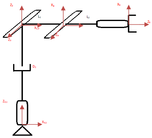
The first step in this is to attach frames to the base and joint positions of the robotic manipulator. The rules for this are simple, but very important for the remaining steps in deriving the kinematic equations. First a base frame (Frame 0) is attached to the fixed pivot or ‘base’ of the robot. After determining the Z-axis for this base frame, the Z axis for the first joint is chosen. This axis will lie along the joint axis, in the case of a revolute it will lie along the axis of rotation, in the case of a prismatic it will lie along the axis of translation. After choosing these, the X axis is chosen as orthogonal to the Zi axis and the Zi+1 axis. The Y axis is ignored as it does not contribute to the DH Parameters. Figure 2 shows the complete joint diagram with the frames attached.
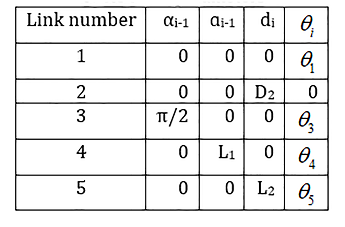
The second step in this is to derive the Denavit–Hartenberg (DH) parameters. These parameters define the convention of how frames have been attached to robotic manipulator. It is known that αi-1 represents the angle about the common normal of Zi-1 and Zi. The length of this common normal is defined as ‘ɑi-1’. ‘di’ refers to the distance from the X axis of the current frame to the next frame along the current frames Z axis. The last parameter is which refers to the angle between the current X axis and the Xi+1 axis about the current Z axis [9]. Following these rules, the DH parameters were calculated and recorded in Table 1 below.
Table 1. DH parameters
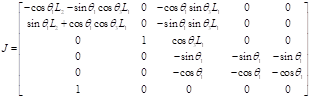
After calculating these parameters, they are plugged into a transform matrix which represents the rotation and translation of a frame with to respect to another one. After calculating the transformation matrix. The Jacobian matrix is found. The Jacobian matrix is used to define the end-effector orientation based on the individual joint angle. It is derived by taking the partial derivative of each joints transfer function with respect to the base. The equation below shows the template used to derive the Jacobian matrix.
4. Dynamic Analysis
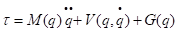
After completing the kinematic equation’s, the next step is to calculate the dynamic equations. The resultant of preforming the dynamic calculations will yield the torque equations. These torque equations will show the torque required at each joint based on the joint positions, and velocities. The dynamic equation is shown below. Where 𝜏 in this case is a 5x1 vector representing the torque at each joint [9].
In this paper the generalized Lagrange approach was used. This method begins by calculating the mass matrix. The mass matrix gives information on the inertia acting upon each joint and the coupling of joints.
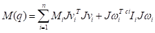
The above equation is used to derive the mass matrix. Jvi and Jwi refer to the equations below.


These equations are similar to the equations used in the kinematics to derive the Jacobian matrix. In the Jw, Ɛ is equal to zero if the joint is prismatic, and 1 if the joint is revolute. As the mass matrix is very long, the calculations carried out to derive it along with the final result is not listed here anymore. After calculating the mass matrix, the velocity matrix is next. The velocity matrix is calculated using the equation below.
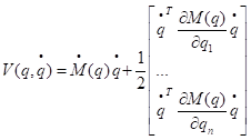
This equation uses the derivative of the mass matrix with respect to time along with the partial derivatives of the mass matrix with respect to each joint. The velocity matrix describes the Coriolis and centrifugal forces felt at each joint.
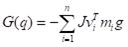
The last of the three equations is the gravitational matrix G(q) that represents the gravitational force acting upon each joint. It is calculated using the formula below.
Plugging these equations into the dynamic equation gives the torques at all joints. In the case of this robotic manipulator, the joints that will experience the most stress are joints 1 and 3.
5. Control Analysis
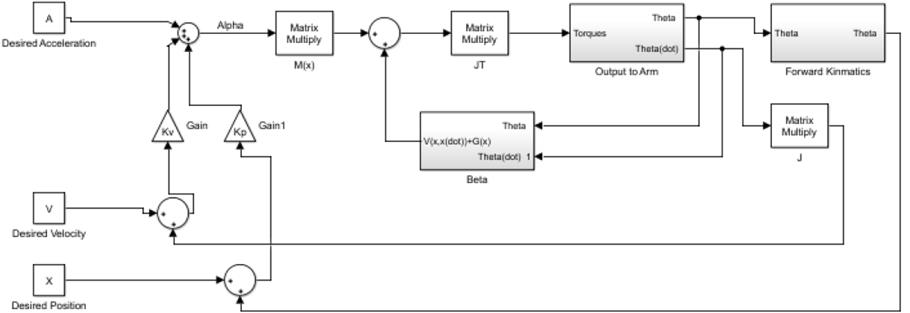
The control law proposed for this robotic manipulator is a non-linear decoupled PD controller. This was chosen for simplicity and to ensure the manipulator would be able to function properly. The control law proposed can be seen in the equation below.


The law uses 𝛼 and 𝛽 to eliminate the uncertainty in the environmental conditions or application of the manipulator. These uncertainties could be an increase in friction over time as the manipulator ages, or changes in masses of the objects being picked up. Figure 3 shows the block diagram for this control law which was created in Simulink. The feedback of the actual velocity and position allows for calculation of the error between the two. Using this error and the proper gains to achieve a critically damped system, the control law will ignore the interaction between joints and tend toward the desired position. The invariant set theorem can be used to prove that this is true [10]. By finding the time derivative of the energy of the system we can see that external power input will be required when the joint velocity and acceleration is not equal to zero. As this system uses error feedback, joint velocity and acceleration will only be equal to zero when the manipulator has reached its desired position.
6. Computer Simulation Results
The computer simulation carried out in this paper was done in SolidWorks. This simulation was done to show the full range of motion that this the manipulator is capable of. To clearly show all motions, joints were moved one after the other in order from joint 1 to 6. After simulating the motion in SolidWorks, the kinematics were simulated in Octave to show the functionality of the equations derived.
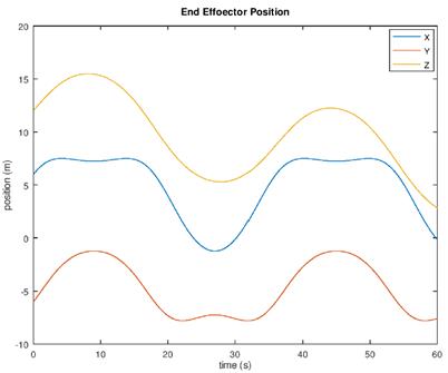
The above graph shows a plot of the X, Y, and Z position of the end effector relative to the base frame after an input of oscillation into the revolute joints and moving the prismatic joint down at a constant velocity. The easiest curve to visualize is the yellow ‘Z’ curve that oscillates up and as the 3rd and 4th revolute joints move back and forth but slowly lowers as the prismatic joint lowers.
Overall, this study discusses the design of a pick and place cylindrical robotic manipulator optimized for processes where parts will be moved from one assembly cell to another located above. A literature review was done to investigate the need for this type of design and the competing designs found in industry today. Manufacturers today are looking at any idea that can drive their costs down. Square footage on a factory floor is utilized with as much efficiency as possible. The possibility of urban manufacturing also drives the need for efficiency as rent in urban spaces can often be the largest contributor to overhead. While cylindrical robotic manipulators have been around for a long time, they lack the range of motion at the end effector that this design will have. Robotic arms presented by companies like Fanuc or ABB offer a greater range of motion however that range of motion comes with the cost of increased footprint. The design for the manipulator proposed in this paper consists of four revolute joints and one prismatic. The prismatic joint can be modified for the robot to reach whatever heights is required.
7. Conclusion
This paper discusses the design of a pick and place cylindrical robotic manipulator optimized for processes where parts will be moved from one assembly cell to another located above. The kinematics, dynamics and control of the proposal robotic manipulator are studied, and the effectiveness of the robot design is verified. The prismatic joint in this design allows for the manipulator to be move up and down the Z axis (world frame) while maintaining a consistent footprint on the ground. The prismatic joint can be modified for the robot to reach whatever heights is required. Future study will focus on building a prototype applying learning control to this robot to handle uncertainties that may occur in the industries.
References
[1] P. Dallasega, M. Woschank, S. Ramingwong. (2019). Field study to identify requirements for smart logistics of European, Proceedings of the International Conference on Industrial Engineering and Operations Management, pp. 844-855.
[2] D. T. Matt, G. Orzes, E. Rauch. (2018). Urban production–a socially sustainable factory concept to overcome shortcomings of qualified workers in smart SMEs, Computers & Industrial Engineering.
[3] S. Kucuk, Z. Bingul. (2004). The inverse kinematics solutions of industrial robot manipulators, IEEE Conferance on Mechatronics, pp. 274-279, Turkey, Istanbul.
[4] K. Krishnamurthy. (1989). Dynamic modelling of a flexible cylindrical manipulator. Journal of Sound Vibration, 132 (1), pp. 143-154. View Article
[5] B. Wei. (2020). Design and Modelling of a Pick and Place Robotic Manipulator. Proceedings of the 7th International Conference of Control Systems, and Robotics (CDSR'20). Virtual Conference - November, 2020, DOI: 10.11159/cdsr20.154 View Article
[6] [Online].Available: View Article
[7] [Online].Available: View Article
[8] [Online]. Available: View Article
[9] J. Craig. (2018). Introduction to robotics, mechanics and control. Pearson (4th Edition).
[10] B. Wei. (2018). Adaptive control design and stability analysis of robotic manipulators. Actuators, 7(4), 89. View Article