Journal of Machine Intelligence and Data Science (JMIDS)

Volume 3 - Year 2022 - Pages 25-35
DOI: 10.11159/jmids.2022.003
Transmitter and Receiver Design for Underwater Communication
Cemil Mervan Atalay1, Murat UCUNCU1
1Başkent University, Department of Engineering Faculty, Electrical-Electronics Engineering Department
06810 Eskişehir Yolu Bağlıca Kampüsü , Ankara, Etimesgut, Turkey 90
cmervanatalay@gmail.com; mucuncu@baskent.edu.tr
Abstract - Today’s technology has begun to improve very fast and communication technology tries to adapt this positive change. Each new innovation of theoretical changes has been trying to be implemented practically. Although it is relatively easier for RF communication to adapt this change, since there are many manufactured special ICs for special tasks, it is still a challenging task for underwater communication. It is very difficult to establish a reliable link for underwater communication due to the lack of receiver designs suitable for underwater communication in the literature. Besides, it takes significant amount of time to implement such algorithms on FPGAs with HDL languages. In this paper, several successful telecommunication techniques of both RF and UWA communication are combined to construct a real time operating end to end UWA system. The proposed system is prepared on MATLAB with System Generator blocks. Therefore, it can directly be implemented on Xilinx’s FPGAs. We explained every step of the design in detail and explain the functions of individual modules used in the system. In this way, the users of the system can tune the parameters according to their system performance requirements.
Keywords: FPGA, Digital Design, Acoustic Communication, Receiver Design, System Generator
© Copyright 2022 Authors - This is an Open Access article published under the Creative Commons Attribution License terms. Unrestricted use, distribution, and reproduction in any medium are permitted, provided the original work is properly cited.
Date Received:2022-09-24
Date Accepted: 2022-10-10
Date Published: 2022-11-24
1. Introduction
The propagation of information underwater is a difficult issue. Today, there are three candidate methodologies stated as communication by using electromagnetic, acoustic or optical waves. Electromagnetic waves can only radiate through extremely short distances (a few meters at 10 kHz) at low frequencies and under the water [1]. Optical communication is another alternative for underwater communication. Optical signals offer high data rates (above MHz) and are best used in the blue-green region (around 500 nm) [1]. However, optical signals cannot propagate beyond 100 meters due to high attenuation problem. Therefore, electromagnetic wireless communication at underwater acoustic communication is considered to be superior to optical communication.
After the propagation methodologies are cleared, in the literature, state of the art telemetry techniques with high speed are discussed [2]-[4]. These researches are mainly focused on how to find a better modulation scheme for underwater communication. Important modulation schemes such as Frequency Shift Keying (FSK), Quadrature Phase Shift Keying (QPSK) [2], Phase Shift Keying (PSK), Quadrature Amplitude Modulation (QAM) [3] and Orthogonal Frequency Division Multiplexing (OFDM) [5] are evaluated in terms of their suitability for underwater transmission. Unfortunately, underwater acoustic channel is very noisy and is not easy to establish a stable communication due to the difficulty to estimate the acoustic channel precisely. For this issue, many researches have been carried out to estimate and model the underwater acoustic channel [5]. Apart from the physical layer, some other researches are focused on the network layer to provide a better underwater communication [6]-[9].
It is strictly necessary to use a FEC (Forward Error Correction) methodology to decrease Bit Error Rate (BER) for underwater communication. Popular FEC methodologies such as Reed Solomon [10] and Polar Codes [11] are implemented for underwater communication systems.
Moreover, some designs in the literature focused on creating a complete receiver system which includes both modulation schemes and forward error correction methodologies. OFDM modulation and Turbo Coding combined in [12] They reach 2.8 Kbps to 9 Kbps data rate with 10-4 Bit Error Rate.
OFDM Modulation is also combined with Polar Coding [11] where 10-7 Bit Error Rate is reached at 7 dB SNR, however with a Polar Coding Rate of 1/4 which means 3/4 of the data consist of frozen bits and only 1/4 bits consist of message bits.
As stated in the previous paragraphs, many modulation schemes, forward error correction methodologies, network technologies and channel estimation techniques are used to improve underwater communication. The common point of all of these schemes is that they all are inspired from RF technology. As RF communication technology improves, underwater communication is also improved.
Although most of the known modulation schemes, FEC and channel prediction methodologies are implemented on underwater communication systems, there is not yet any end to end real time underwater system implementation in the literature which combines techniques to present a novel system to overcome problems such as multipath. In this paper, we developed a novel end to end real time underwater acoustic communication system. Since this system’s physical layer is inspired from RF 5G Technology, we termed the developed system “Underwater 5G Technology”.
Underwater 5G Technology is a novel underwater acoustic communication system which offers a stable point to point communication with a significantly less Bit Error Rate as compared to the existing technologies. In this paper, both the transmitter and receiver side of this technology is designed and implemented. The digital design of all the components of the transmitter and receiver are carried out by using MATLAB System Generator, implemented on Xilinx’s ZYNQ-7020 FPGA. The whole design is also tested and verified practically by using a water tank test set up.
2. Design and Simulation
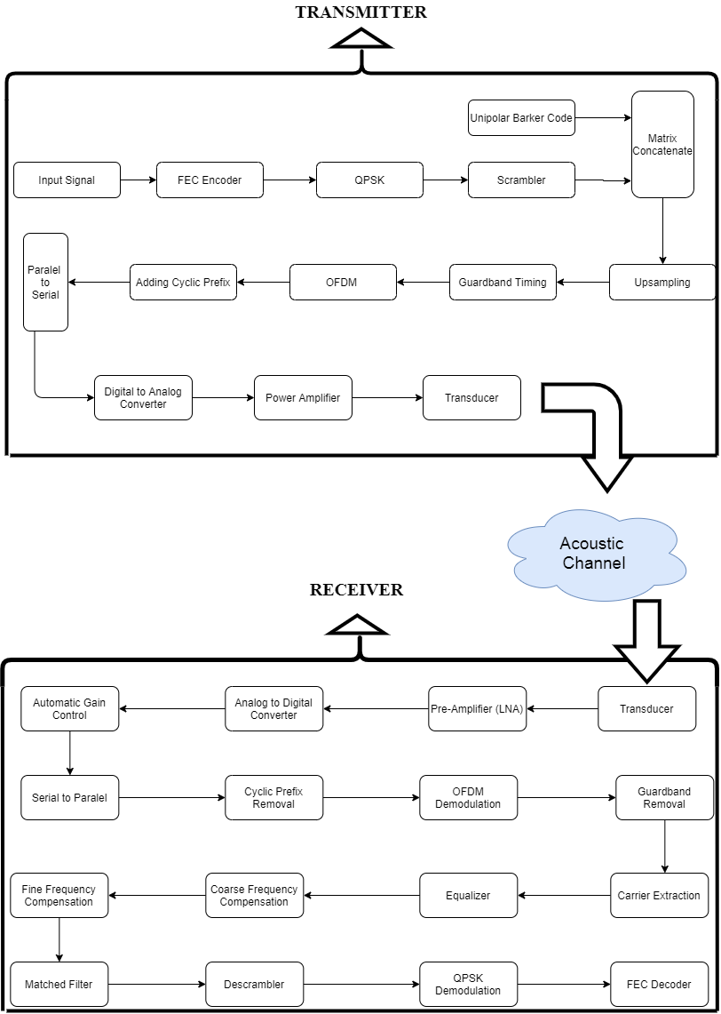
The digital design of the system consists of three major parts on the transmitter side. The first part is the Input Sampling Part (ISP). ISP accepts data to the system at pre-determined (adjustable from 40 kHz to 100MHz) frequencies. The second part is the symbol creation part which provides forward error correction encoding and afterwards QPSK modulation is activated for sub-modulation of OFDM. The last stage is the OFDM modulation part. After all of these three operation stages, the signal is ready to transmit.
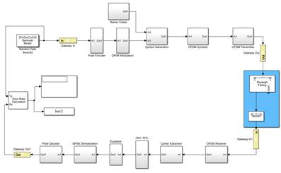
The Receiver side of the proposed digital design is more complex than the transmitter side. It consists of several subsystems. The first part is the OFDM receiver. Then, the data is extracted and equalized with Zero-Force equalizer. After the equalization, coarse frequency compensation and fine frequency compensation are applied to the received signal. Frequency compensation operations are carried out after the FFT and Equalization processes since there are as much as thousands frequency channels before the FFT process and it is a challenging task to apply compensation process to that raw data. Finally, decoding is performed. Each module function is detailed in the subsequent sections. Below, the overall diagram of the system is given in Figure 1.
3. Digital Design of the Transmitter
In this paper, several simulations were carried out by using MATLAB software and the system was implemented on Xilinx’s FPGA. Therefore, the system is designed by System Generator blocks on MATLAB. The proposed design is suitable to create a valid Axi-Peripheral IP which can be implemented on any Xilinx’s FPGA. The design includes only the basic elements such as logic gates, adders and delay elements. However, the basic blocks sometimes are not enough to implement the desired algorithm. In such cases, Black Box block of System Generator is used. When one writes a code block by using VHDL language, the code block with a few modifications can be used as part of MATLAB simulation with the help of “Black Box” block of System Generator. Therefore, in the digital design of our novel system which is called Underwater 5G Technology, System Generator blocks were only used to make the system directly applicable to any Xilinx’s FPGA [13].
3. 1. Input Sampling
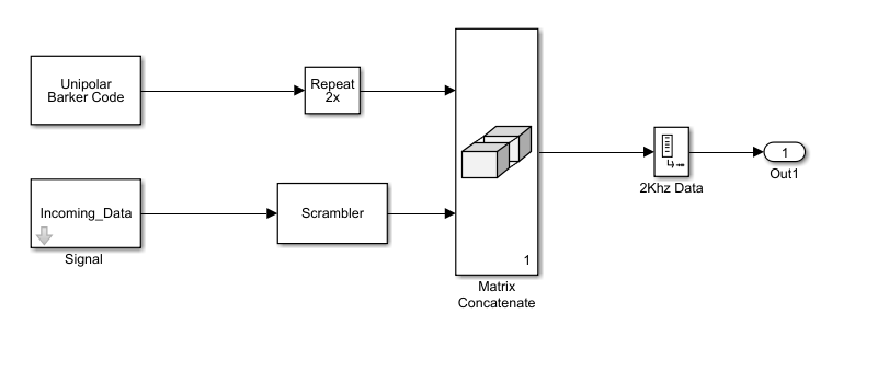
On the transmitter side, incoming data are sampled with 48 KHz. However, the incoming bits are not directly passed through the transmitter system. They are scrambled via a polynomial before sending the bits to the transmitter. The objective of the scrambling is to decrease the number of consecutive 1’s or 0’s in the transmitted signal because long sequence of 1’s or 0’s can cause synchronization problems in the transmission.
Symbol Creation part includes two processes as modulating the message signals and generating the “ready to send” symbols. The candidate modulation types are Binary Phase Shift Keying (BPSK), QPSK and 4QAM with two-dimensional Gray Scale Mapping [2]-[3].
3. 2. Symbol Creation with QPSK
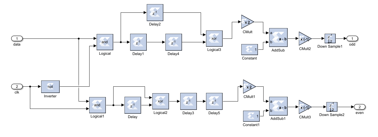
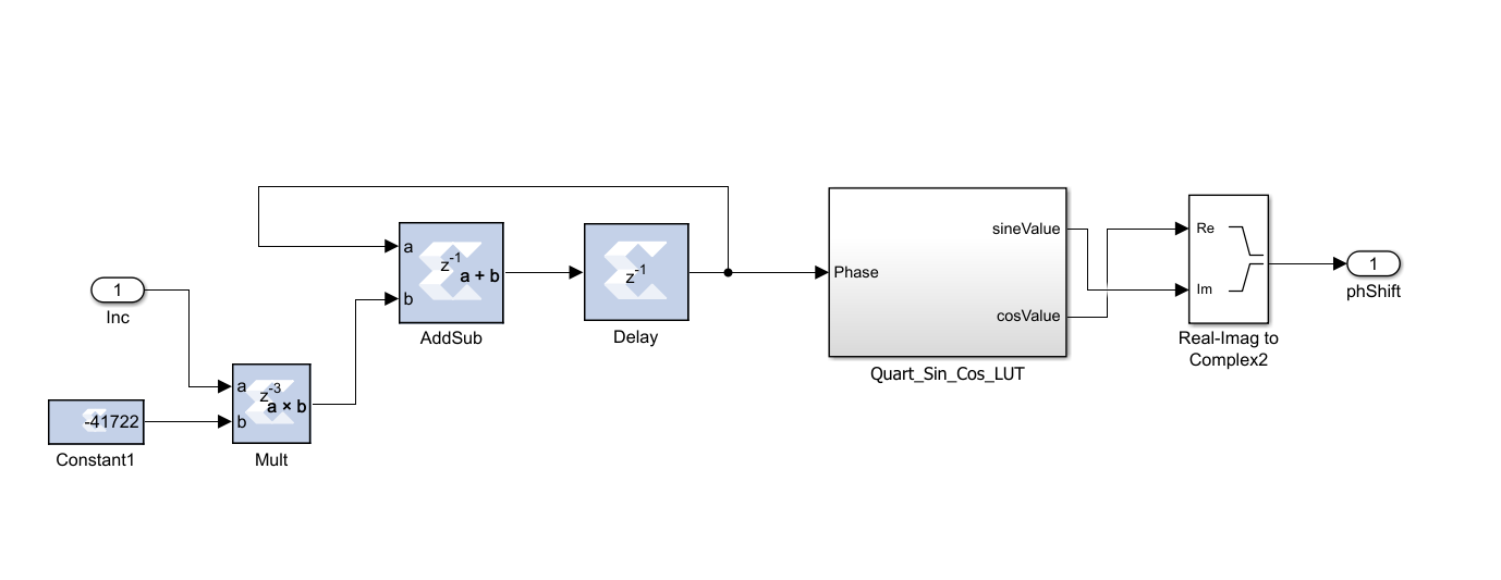
QPSK vs QAM performance analyzes are done in many literature resources [14] in which we understand that QPSK gives better efficiency in a noisy underwater acoustic multipath channel with a high probability. For this reason, only the QPSK modulation is implemented with System Generator blocks and will be implemented on FPGA as a part of Underwater 5G System . In this paper, Offset QPSK (OQPSK) is decided to be the modulation scheme since it decreases amplitude fluctuations and establishes more stable signals for OFDM modulation. In the OQPSK, the offset may be chosen as, π/4, π, 3π/4 and etc. In our design, 3π/4 offset is chosen for OQPSK. MATLAB System Generator Design of the OQPSK is shown on below Figure 2.
3. 3. Forward Error Correction
The Polar Codes are chosen for the Forward Error Correction (FEC) Methodology. FEC is one of the most important part of Underwater 5G Technology. It decreases BER significantly. The Polar Codes are also chosen for RF 5G Technology. Polar Codes has attracted so much attention recently that it is chosen as the 5G communication standard. The polar codes implementation for 5G by 3GPP community is still going on [15]. However, research on the performance analysis of the Polar Code implementation for UWA communication is mature and there is only one research on this issue [11]. Therefore, it is difficult to comment on the Polar Code performance. In this paper, Polar Codes are chosen to be used for our design to see and contribute to the implementation performance. For the digital design of the FEC, Black Box is used and VHDL code is inserted to the Black Box.
3. 4. Barker Codes
To receive a signal especially from a noisy channel, the receiver must know that the incoming signal is not noise and the signal is worth to be decoded. For this purpose, Barker codes are used in the early generation of RF communication with low data rates such as 1-2 Mbps in the 802.11 standard. Barker codes are not preferred to be used in Today’s RF technology. However, Barker codes may be useful since UWA works on slow data rates such as 0-100 kbps. Therefore, we decided to use barker codes at the receiver side in this thesis. Autocorrelation function or a match filter can detect barker codes at the receiver side where the beginning of the frame can be detected. After the incoming data is scrambled according to a predetermined polynomial, Barker codes are added at the start of all frames as a preamble. The length of the frames is selected as 384 bits. The details will be discussed in the OFDM transmitter subsection. Each frame includes 384 bits and 26-bit barker code as a preamble is added onto each frame. A match filter checks all the incoming data on the receiver side and if the barker code length is bigger than a threshold value, the frame will be accepted as a valid frame. The use of scrambler and Barker codes are shown in Figure 3.
3. 5. Orthogonal Frequency Division Multiplexing (OFDM) Transmitter
OFDM has recently been used for underwater acoustic communication due to its robust characteristics for channels that require long propagation delay. Cyclic Prefix and Guard Time features of OFDM facilitates robust communication and provides immunity to inter symbol interferences. The determination and design of cyclic prefix is discussed in the following sections. Here, we can confidently state that it is possible to establish a good and robust underwater communication link by a properly selected Cyclic Prefix. Since OFDM divides the spectrum into many sub channels with overlapping narrow subbands, symbol duration becomes relatively long compared to the multipath spread of the underwater acoustic channel. As a result, Inter Symbol Interference might be neglected in each subband which simplifies the receiver complexity on the receiver side significantly. This phenomenon motivates researchers to work on OFDM in UWA channels. Therefore, OFDM is a suitable candidate for underwater acoustic communication.
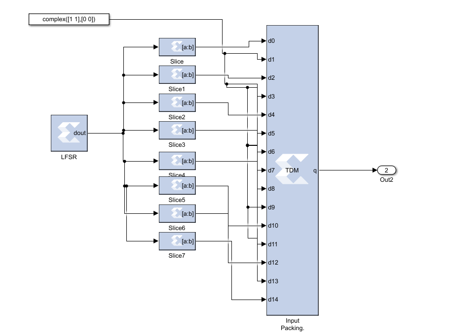
The first stage in the design of OFDM transmitter is the creation of symbols with QPSK modulation and Forward Error Correction. The second stage is the up-sampling application by a factor of 1/12. This process is called Inverse Finite Fourier Transform (IFFT) input packing. The data for which IFFT is performed is packed before the up-sampling process. The details of up-sampling process are shown in Figure 5.13. Here, pre-defined up sampling model is not used. Rather, for every 12 bits pair of data, 12 bits of complex signal is inserted to the system is shown in Figure 4.
This OFDM structure is termed as the Inverse Finite Fourier Transform (IFFT) process. IFFT of the baseband symbols creates OFDM symbols. In the previous process, input is packed for the OFDM and it becomes ready for the IFFT. However, there is one more additional step for the OFDM which is the addition of guard bands to the message signal. This additional step is crucial for underwater 5G technology. Guard bands prevent the Inter Channel Interference (ICI). For the underwater 5G technology, we chose lengths of the guard bands to be 20 ms. We chose this 20 ms with the help of Monte-Carlo simulation methodology. We simulated our system with guard bands and reached least ICI with 20 ms. After the guard bands are created, IFFT of the message signal is performed. Finally, CP is added to the end of the transmitted signal. The whole process is shown in Figure 5.
In the System Generator Block, we can directly add Black Box and prepare embedded VHDL code for Black Box to perform the specific task. For the guard band generation, a VHDL code block is prepared and it is inserted into the Black Box. VHDL code block is not enough alone. It is also necessary to prepare a MATLAB code for the Black Box to make it work as desired. Black Box design is depicted in Figure 6.
Final part of the OFDM transmitter is the transition to the pass band. This process carries base band signal to pass band. There are several options for this process. Base Band to Pass Band process is chosen to be implemented (Figure 7) for the underwater 5G technology.
4. Digital Design of the Receiver
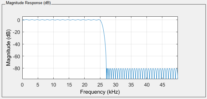
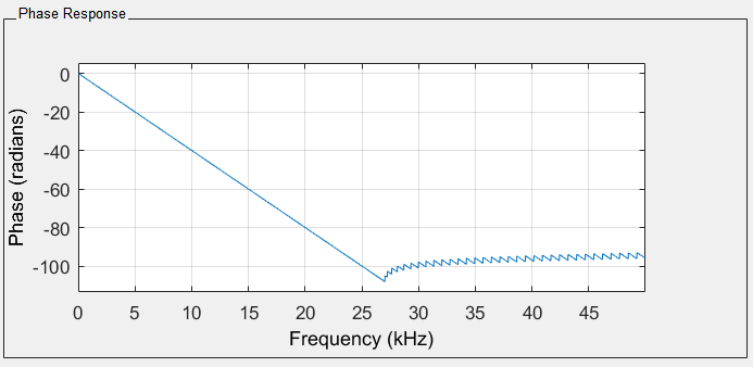
The main objective of the receiver is to have the incoming data with minimum noise as minimum as possible. There are two main modules which play crucial roles in the design of the receiver. The first module is a well-designed low pass filter to remove the ambient noise. In this paper, the low pass filter is designed by using the Filter Designer and Analyzer (FDA) module of the System Generator. Once the ideal low pass filter is designed, FDA determines the filter coefficients which are easily adapted to the filter. Designing a robust filter is not trivial since there are many tradeoffs such as the order of the filter and its superior free dynamic range. After trying several implementations, a low pass filter with an excellent performance for underwater 5G technology is designed and implemented. The order of the filter is 201. The order of the filter is relatively high. It is chosen in that way to increase spurious free dynamic range and since we used ZYNQ FPGA, this order of filter doesn’t cause any memory related problems. The Magnitude and the Phase response of the filter is shown in Figure 8 and Figure 9.
4. 1. Gain Control
The second module is the gain control and the normalization operations module. To treat each data equally, they have to be normalized. In addition, the signal level should be controlled by a gain controller. Then, Cyclic Prefixes must be detached from the incoming signal. The digital design of this gain control and normalization of OFDM receiver for underwater 5G technology is shown in Figure 10.
4. 2. OFDM Receiver
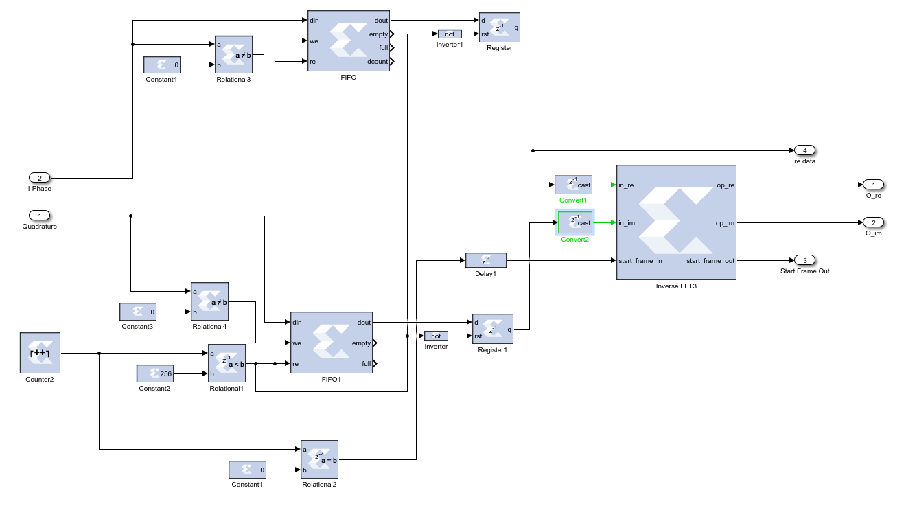
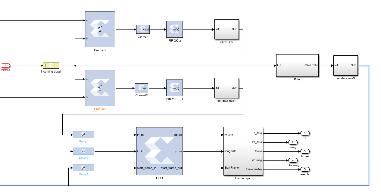
Once the signals are normalized and filtered, the next thing is to convert OFDM symbols to the QPSK symbols. Each OFDM symbol is carried via a different channel, to create these channels, we used IFFT on the transmitter side to create a frequency bin from these multiple channel streams. On the receiver side, the carriers must be extracted and mentioned frequency bins must be divided into different streams again. For this purpose, we applied FFT to the incoming signal. FFT process extracts the symbols. However, there are residual guard bands which were added on the transmitter side. Location of the guard bands are saved in a memory unit which is a trivial task. Digital Design of the FFT process is shown on Figure 11.
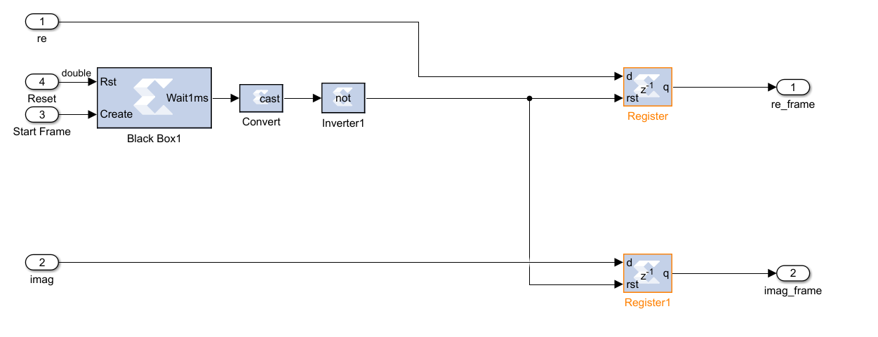
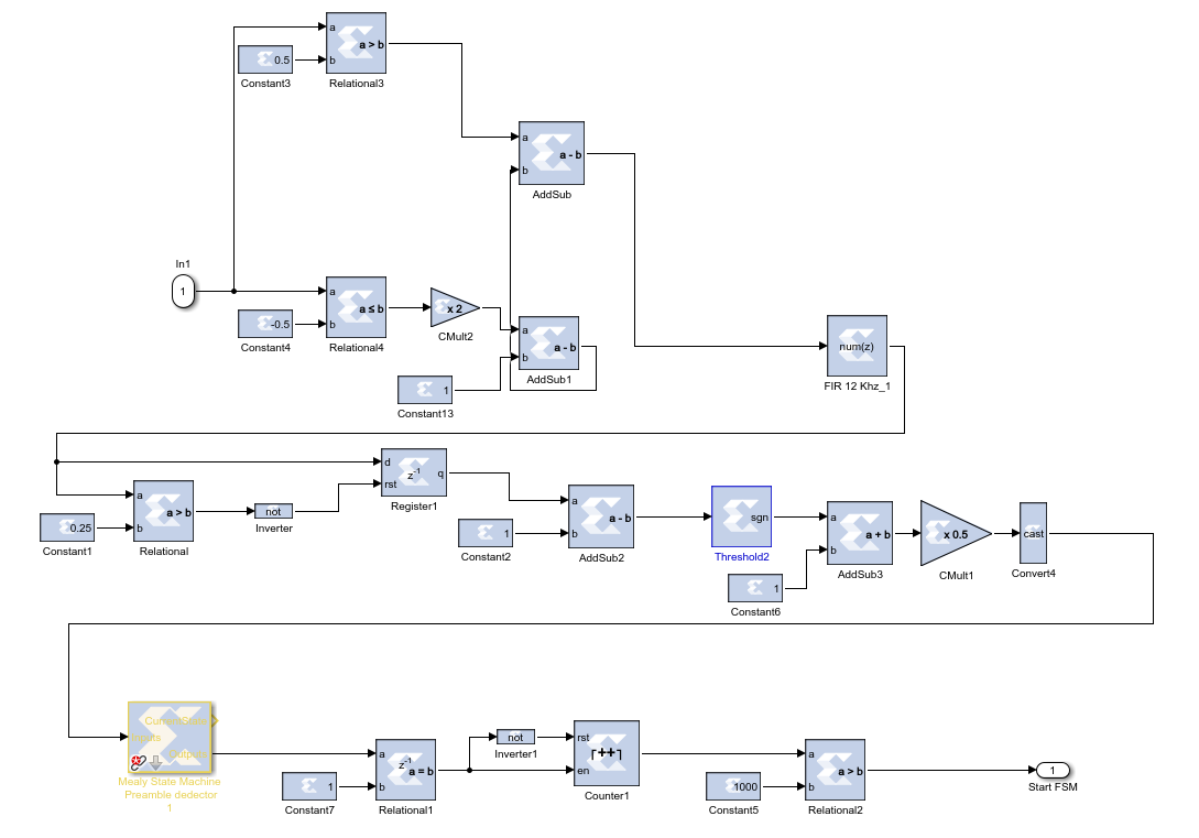
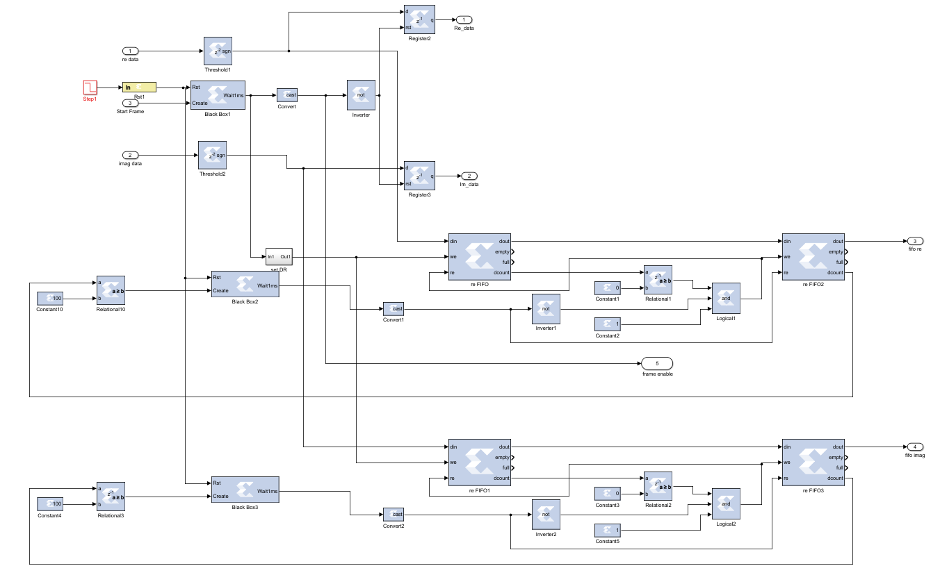
Taking FFT with the System Generator block is not the same as a normal FFT process, the system must know the right time for the start of the FFT process. Otherwise, the FFT doesn’t give the desired symbols. For this purpose, a Frame Synchronization Block is designed. This design helps to detect the valid frame for the remaining part of the receiver. Digital design of the frame synchronization is shown in Figure 12.
4. 3. Acoustic Channel Estimation
First part of the estimation is the channel equalization part. With the help of a proper equalization methodology, baseband QPSK symbols are reconstructed and this process enables the work compensation methodologies. Without proper channel equalization, we cannot apply any compensation or decoding algorithms since the signals are corrupted. After the equalization process, the received signal becomes ready to be corrected in terms of phase and frequency offsets. Then, two important blocks are designed. The first one is the Coarse Frequency Compensation which estimates and corrects the phase and frequency offset. The second block is the Fine Frequency Compensation block which corrects residual components of frequency and phase offsets.
Finally, no special digital design is made for the Doppler Effect since the transmitter and receiver is assumed to be settled to fix points. It is eliminated by the low pass filter at the start of the receiver and compensated with the guard band in the message.
4. 4. Acoustic Channel Equalisation
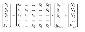
Without a proper equalizer, the system cannot establish a good communication. This Equalizer is one of the most important part of the UWA communication system. As proved earlier, we have to estimate the channel and then we have to equalize it. The received signals can be expressed in terms of channel response and incoming signals as in Equation 1.

Here, Y represents the incoming symbols through the acoustic channel, X represents the plot symbols matrix, H is the frequency response of the acoustic channel and V is the ambient noise. Open-form of the matrices are given in Equation 2.
There are many channel estimation methods used for the OFDM such as Minimum Mean Square, Linear Mean Square and Least Square. For the Underwater 5G Technology, Least Square method is chosen to be used as the estimation methodology for the equalizer. The Least Square method estimates "H" ̂ to minimize the cost function given in Equation 3 below.

Solution of this Least Square channel estimation is given in (4):

After the Least Square Estimation is applied, the solutions give us the taps of the multipath channel. These solutions are directly used in the equalizer.
For the digital design of the Equalizer, a Black Box is used from the System Generator Toolbox. Inside of this Black Box, VHDL code is generated to make the calculation of the given Equalization process.
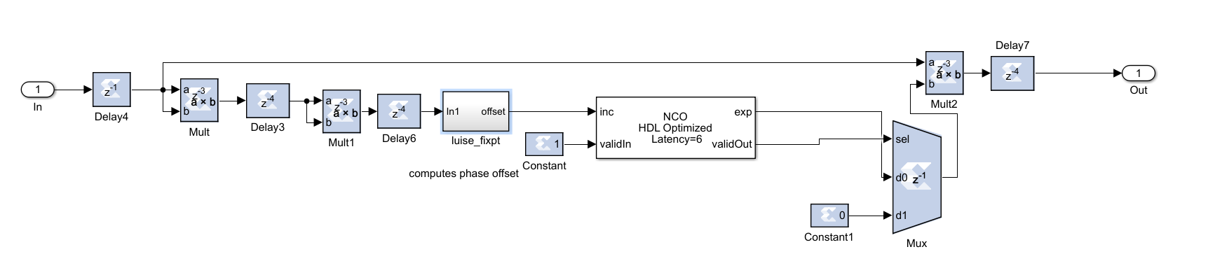
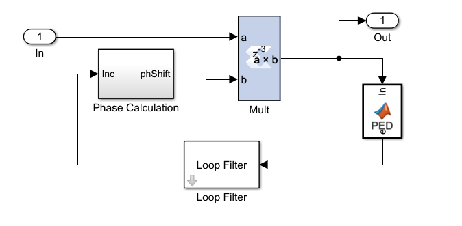
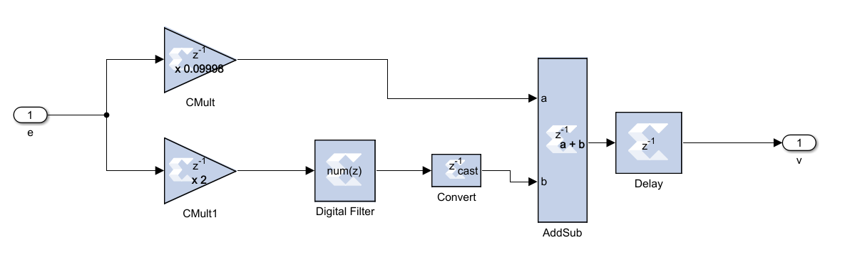
4. 5. Fine Frequency Compensation
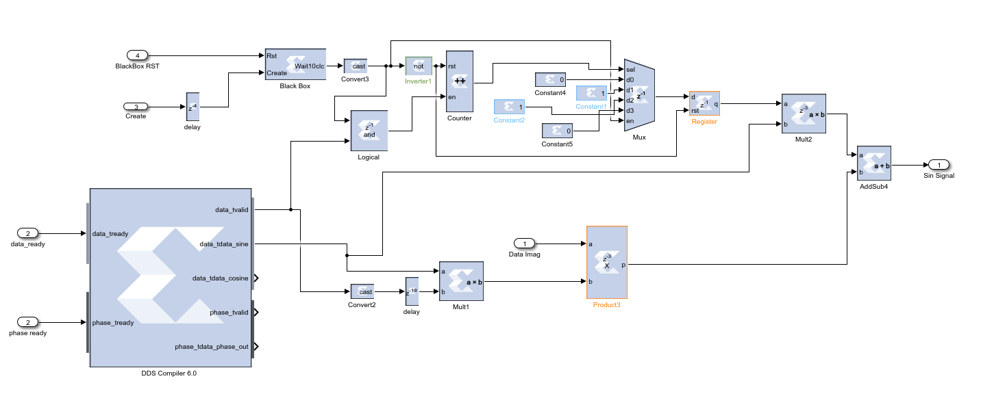
As mentioned in the previous section, although Coarse Frequency Compensation block corrects the frequency offset, it creates a residual frequency offset which rotates the constellation. Fine Frequency Compensation (FFC) is used in underwater 5G Technology to fix this problem. In the FFC algorithm, simply a PLL is implemented to track the residual frequency offset and the phase offset. Then as an estimator, maximum likelihood estimator is used which generates and calculates the phase error. For this purpose, a predefined MATLAB block is used. After that a Loop Filter is used to filter the calculated phase error and then phase calculation block corrects the residual frequency offset and the phase offset. Digital design of these blocks are shown on Figure 14, Figure 15 and Figure 16.
4. 6. Message Decoding
As it is explained in the transmitter part, Barker Codes are attached to the header of the message signal. Therefore, in the decoding part, the Match Filter detects the start of the signal. Match filter has a very basic digital design shown in Figure 17.
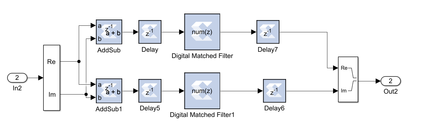
“Digital Matched Filter” block in Figure 17 is a standard FIR filter which uses a set of Barker Codes that are modulated by QPSK as a reference model for the correlation. However, Match Filter block design is not enough to calculate the correlation degree. To calculate the correlation, Equation (5) must be performed.

Here in (5), I and Q symbolize the in-phase and quadrature components of the signal. It is hard to take the square root in the FPGA design, therefore to perform the task given in the above equation; the output of the match filter is connected to a “Square root” block. This block uses a logical technique to make the equation easy to implement on FPGA. Correlation can be approximated with this technique as:

In Equation 6 “L” represents the maximum number of In-phase and Quadrature and “S” represents the minimum number of In-phase and Quadrature. After the correlation value is calculated, it is compared with a threshold value. If the output is bigger than the threshold value, the data is considered to be valid and can be demodulated. Threshold must be chosen carefully, because the small value can cause false alarm while the high value of the threshold may cause to lose the incoming signal. Barker Code length is chosen to be 26 on the transmitter side. Therefore, threshold value must be chosen accordingly. With the help of Montecarlo simulation methodology, we determined the best threshold value to be 16 for the underwater 5G technology since it prevents false alarms.
4. 7. QPSK Modulation
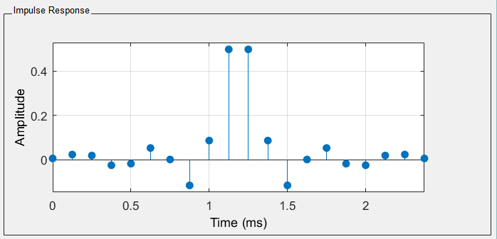
Window function design technique is used for the Low-pass filter design of QPSK demodulator. The window function design method basically selects the desired filter with the ideal frequency characteristics. Then, it truncates its impulse response to generate a Low Pass filter of linear-phase. Impulse response of the designed filter is shown in Figure 18.
After the filter is designed, the output symbols are predicted. For this prediction, there are two commonly used decision theorems in the literature which are Soft Decision and Hard Decision. In information theory, Soft Decision methodology, the incoming data is decoded by considering a list that consists of possible decoded values of the data. Although this decision theorem may result in better bit error rates, it increases the complexity of the design. In this thesis, we used Hard Decision theorem which simply compares the incoming data with the candidate outputs and checks the hamming distances among them. Most similar candidate output is decided to be final decoded data.
4. 8. Polar Code Decoding
Successive Cancellation Decoder algorithm is proposed by Erdal Arikan for the first time [16]. Basically, the decoding process starts from the right hand side of the graphical representation of the encoding in Figure 19, from right to left and from bottom to the top sequentially. Bold face lines are inspected paths [17].
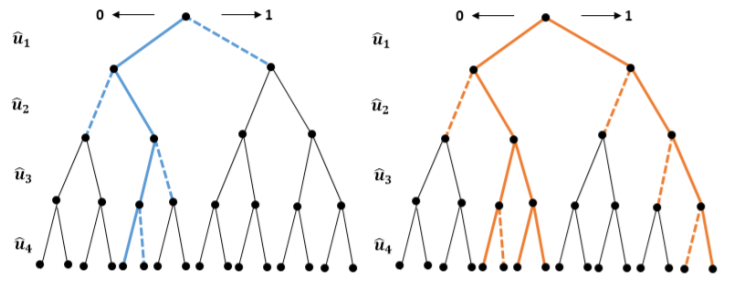
It successively tries to estimate information bits from the channel outputs. For the proposed system, Successive Cancellation List Decoder (SCL) Algorithm is used as FEC methodology. SCL Algorithm has many similarities in terms of the algorithm with Successive Cancellation (SC) Algorithm with a significant difference which is the generated list. SCL algorithm generates a list of “L” which holds candidate code words. Candidate code words are chosen from the values of ![]() for the information bit locations. From the beginning of the calculation, only the determined number of best paths survives and the others are neglected. At the end of the calculation process, best path is chosen from this list and it is served as a decoded bit. For the underwater 5G Technology, SCL Decoder is chosen to be the Polar Decoding algorithm because it gives better results than SC decoder as stated in [18]. Representation of SC against SCL decoder is shown in Figure 20. As shown on the graphical representation, while the SC chooses one path, SCL decoder holds a list of possible paths. Bit error rate decreases with SCL decoder with the help of this list.
for the information bit locations. From the beginning of the calculation, only the determined number of best paths survives and the others are neglected. At the end of the calculation process, best path is chosen from this list and it is served as a decoded bit. For the underwater 5G Technology, SCL Decoder is chosen to be the Polar Decoding algorithm because it gives better results than SC decoder as stated in [18]. Representation of SC against SCL decoder is shown in Figure 20. As shown on the graphical representation, while the SC chooses one path, SCL decoder holds a list of possible paths. Bit error rate decreases with SCL decoder with the help of this list.
5. Simulation Results
Digital Design of the blocks shown in Figure 1 are implemented to compose the complete transceiver design. The final stage of the simulation for underwater 5G technology is the performance evaluation part. The Transmitter and the Receiver of the system are connected by an acoustic channel and they are connected to a bit error rate calculation block. The overall design is shown in Figure 20.
To discuss the performance of the receiver, the constellation outputs of some important blocks are evaluated below. Channel output and equalization process are shown in Figure 21. As it is shown, noisy data comes out of the channel. After the carrier extraction, the symbols are scattered to the diagram. However, it is a normal phenomenon because there are hundreds of symbols in OFDM modulation scheme. After the carrier extraction processes, the Equalizer estimates the channel successfully and corrects the constellation diagram.
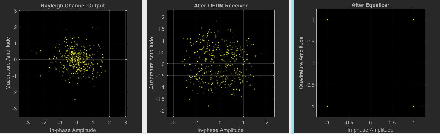
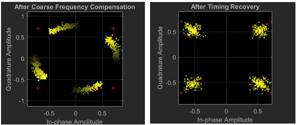
Although in part (c) of Figure 21 looks like correct, the symbols don’t represent the real values. For this purpose, compensation processes were carried out and the output of that processes are shown on Figure 22. As it is explained above, after the Coarse Frequency Compensation, a rotation occurs in constellation diagram. To fix this issue, Fine Frequency Compensation was used. Final constellation diagram are shown on part b of Figure 21.
There are many adjustable parameters for the proposed system such as FFT Length for OFDM, the type of QPSK modulation, Guard Band Timing, Barker code length, Scrambler’s polynomial and etc. All of these can be re-adjusted which causes many cases that must be compared with each other. In this thesis, as an optimal design and for the sake of achieving a meaningful conclusion, all parameters are fixed except the Polar Code.
Table 1. System Parameters.
|
frame length |
1024 bits |
|
cyclic prefix rate 1 |
1/3 & 1/4 |
|
polar code rate |
½ ( 512 bits ) & 5/8 ( 640 bits ) |
|
modulation type |
OFDM |
|
symbol generation |
QPSK |
|
transmission frequency |
20 kHz to 30 kHz |
|
guard band time |
20 ms |
|
preamble |
26 bit barker code |
|
data rate |
30 kbps to 60 kbps |
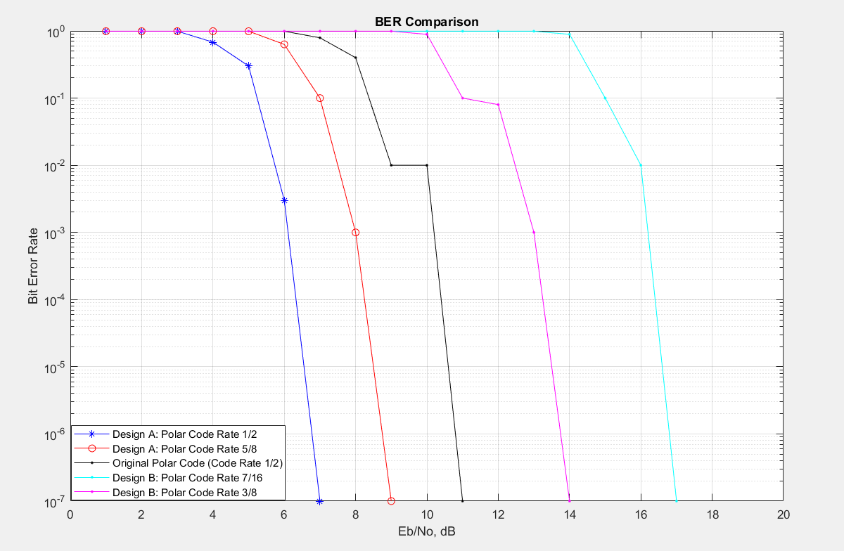
Rate that indicates the ratio of information bits to total number of bits and the Cyclic Prefix rate that indicates the portion of the transmitted signal added to its tail as a cyclic prefix. The bit error rates graph for the Underwater 5G Technology for different Polar Code and CP rates are shown on Figure 23. Monte-Carlo methodology is used for the simulation. The other fixed parameters are shown in Table 1.
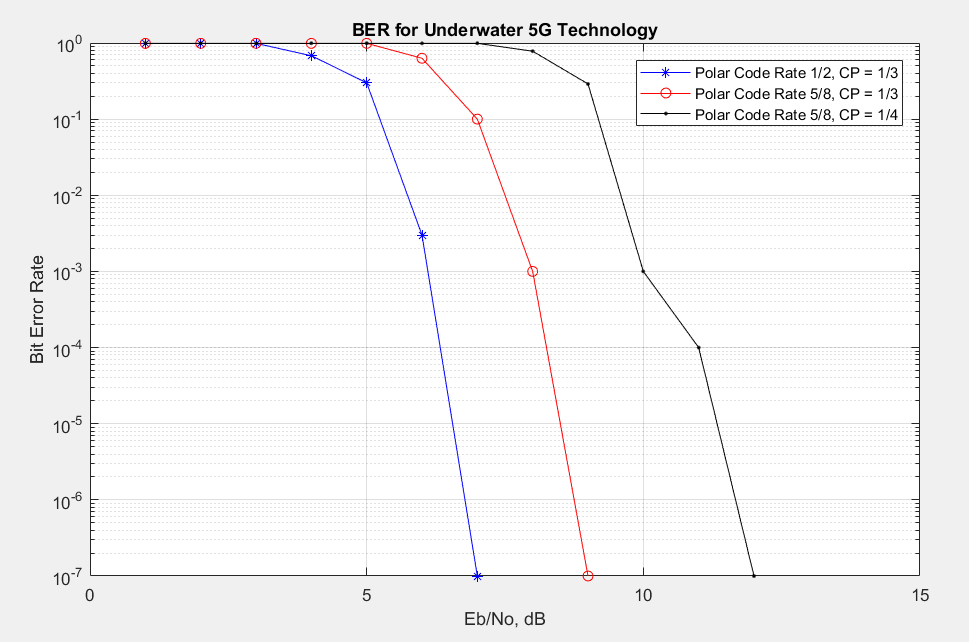
The rate of the Polar Code determines the entropy of the communication. When the rate is 1/2, it means that only half of the transmitted signal includes the information and the other half represents predetermined frozen bits. The system operates between 30 Kbps to 60 Kbps which is considered as a moderate data speed in the literature. Therefore, this kind of polar code rating with this data rate is acceptable. Therefore, the BER graph which is shown in Figure 23 indicates that Underwater 5G Technology works very well. The blue line of the graph which symbolizes the communication with a Polar Code Rate of 1/2 shows that the underwater communication can start when the Eb/N0 rating is approximately 5 dB which is a very noisy channel. Although the communication starts at nearly 5 dB, the best performance of the transaction is achieved at 7 dB Eb/N0 rating. This result shows that after the communication is started, even if it is very noisy environment, the end to end Underwater 5G Technology rapidly recovers the data which is exposed to heavy noise and the system offers the end users a clear communication.
For the comparison, an UWA communication system which uses Turbo Codes for the FEC methodology has reached 2.8kbps to 9kbps with 10-4 BER [12], while our proposed Underwater 5G Technology system has reached 30kbps to 60kbps with 10-5 BER. On the other hand, in the literature, Polar Codes with OFDM is used for UWA Communication systems [11]. Although they don’t present an end to end system, they have used OFDM and Polar codes in the physical layer. They have reached 10-7 BER while the SNR was 11 dB with a polar code rate of 1/2 [28], while our system can reach this BER with 6 dB SNR with the same polar code rate, which means that our system performs better in a worse SNR environment with a better rating of the polar codes. The comparison is shown on Figure 24. It can be easily recognized that our system not also starts sensing the incoming signal earlier but also it performs better in low SNR.
6. Conclusion
In this paper, we have presented a complete end-to-end underwater acoustic communication system which operates in real time. Since this system combines the physical layer of 5G technology with known acoustic communication techniques, we called it underwater 5G technology. Underwater 5G Technology aims at maintaining a robust underwater communication link by overcoming the two main obstacles, Scattering and Multipath. For this purpose, a complete digital design is proposed in this paper. Designed transmitter and receiver include all the necessary modules for a reliable underwater communication. This communication is called as underwater 5G communication because it imitates all the necessary parts of RF 5G Technology successfully. The proposed system also provides very good performance in terms of speed and low SNR.
References
[1] N. Farr, A. Bowen, J. Ware, C. Pontbriand, M. Tivey, "An integrated underwater optical/acousstic communications system," in Proc. Oceans 2010 IEEE, DOI : 10.1109/OCEANSSYD.2010.5603510, Sydney, 2010. View Article
[2] D.B. Kilfoyle, A.B. Baggeroer, "The state of the art underwater acoustic telemetry," IEEE J. Oceanic Engineering," vol.25, pp. 4-27, 2000. View Article
[3] M. Stojanovic, "Recent advances in high-speed underwater acoustic communications," IEEE J. Oceanic Engineering, vol.21, pp. 125-136, 1996. View Article
[4] L. Freitag, M. Stojanovic, D. Kilfoyle, "High-rate phase-coherent acoustic communication : a review of a decade of research and a perspective on future challenges," in Proc. 7 th European Conf. on Underwater Acoustic, 2004.
[5] A. Radosevic, R. Ahmed, T. Duman, J.G. Proakis, M. Stojanovic, "Adaptive OFDM modulation for underwater acoustic communications," IEEE J. of Oceanic Engineering, vol.39, no.2, pp. 373-370, 2014. View Article
[6] E.M. Sozer, M. Stojanovic , J. Proakis, "Underwater acoustic sensor networks," IEEE J. of Oceanic Engineering, vol.25, pp.72-83, 2000. View Article
[7] I.F. Akyıldız, D. Pompili, "Underwater acoustic sensor networks," Elsevier Ad Hoc networks, vol.3, pp.257-279, 2005. View Article
[8] J. Heıdemann, W. Ye, J. Wills, A. Syed, Y. Li, "Research Challenges and Applications for Underwater Sensor Networking," in Proc. IEEE Wireless Com. And Networking Cenference," 2006. View Article
[9] J.H. Cui, J. Kong, M. Gerla, S. Zhou, "The Challenges of Building Scalable Mobile Underwater Wireless Sensor Networks for Aquatic Applications," IEEE Network, Special Issue on Wireless Sensor Networking, 2006.
[10] M. Asif, M.R. Arshad, A. Yahya, "Execution of Reed Solomon Coding as Forward Error Correction in Underwater Acoustic Communication," 2008.
[11] G. Qiao, S. Xing, F. Zhou, "A Multi-User Detection Scheme Based on Polar Code Construction in Downlink Underwater Acoustic OFDM Communication System," IEEE Access, vol.7, 2019. View Article
[12] Waves, "Physical radio channel models". View Article
[13] MathWorks MATLAB®, "Xilinx System Generator for DSP". View Article
[14] J. Xavier, D.M. Julio, "Modulation Analysis for an Underwater Communication Channel", M.Sc. thesis, Faculty of Engineering of the University of Porto, Porto, Portugal, pp.23-24 ,2012
[15] MCC Support, "Final Report of 3GPP TSG RAN WG1 #87 v1.0.0," Feb 2017. [Online].Available: View Article
[16] E. Arikan, "Channel Polarization: A Method for Constructing Capacity-Achieving Codes for Symmetric Binary-Input Memoryless Channels," IEEE Transactions on Information Theory, vol.55, no.7, 2009. View Article
[17] M. Stojanovic, "On the Relationship Between Capacity and Distance in an Underwater Acoustic Communication Channel," in Proc. 1st ACM International Workshop on Underwater Networks, pp.41-47, 2006. View Article
[18] J. Huang, J. Sun, C. He, X. Shen, Q. Zhang, "High-Speed Underwater Acoustic Communication Based on OFDM," in Proc. IEEE International Symposium on Microwave, Antenna, Propagation and EMC Technologies for Wireless Communications Proceedings, 2005.