Journal of Machine Intelligence and Data Science (JMIDS)

Volume 2 - Year 2021 - Pages 25-32
DOI: 10.11159/jmids.2021.004
An Experimental Set-up and Performance Evaluation of EPON-Based 5G RAN Architecture Enabled by Distributed Network Control Management
Syed R. Zaidi1, Aparicio Carranza2
1Bronx Community College of the City University of New York
2155 University Avenue, Bronx, NY, USA
syed.zaidi@bcc.cuny.edu
2New York City College of Technology of the City University of New York
300 Jay Street, Brooklyn, NY, USA
acarranza@citytech.cuny.edu
Abstract - The multifaceted technological boom as driven by mobile and IoT devices requires more bandwidth by the day. Some applications such as gaming and real-time streaming services in ultra-high definition have higher bandwidth as well low latency requirement. The only viable solution for these data hungry applications is fiber-wireless (FiWi) network architecture. Though numerous hybrid Fiber-Wireless network architectures have been expected to utilize the fiber-based Passive Optical Network (PON) access infrastructure to backhaul mobile traffic, most of these architectures, however, have utilized the typically centralized tree-based PON topology, which can only support a centralized Radio Access Network (RAN) architecture. A converged PON-5G access infrastructure must be capable of supporting a distributed architecture as well as distributed Network Control and Management (NCM) operations. The major weakness is that mainstream PONs are typically deployed as tree topologies and the tree-based topology can neither support the distributed access architecture nor intercommunication among the access nodes (ONUs) attached to the PON. In this study we devise a fully distributed Ring-Based EPON architecture that enables the support of a converged PON-5G LTE access networking transport infrastructure utilizing distributed network control management to seamlessly backhaul both mobile and wireline multimedia traffic and services. An experimental set-up is also employed to measure BER and eye diagram of the proposed architecture.
Keywords: PON, FiWi, 5G, RAN, EPON.
© Copyright 2021 Authors - This is an Open Access article published under the Creative Commons Attribution License terms. Unrestricted use, distribution, and reproduction in any medium are permitted, provided the original work is properly cited.
Date Received:2020-06-28
Date Accepted: 2021-07-15
Date Published: 2021-08-04
1. Introduction
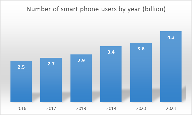
The demand for mobile wireless communication services is increasing steadily. Mobile technology is universal and growing. The number of smart phone users is expected to scale beyond 4 billion by 2023, refer to the Figure 1 [1] and the global mobile workforce is expected to reach 1.87 billion by 2022 [2]. The projected total number of global mobile subscribers grown from 5.1 billion to 5.7 billion in 2018, which is 71 percent of world population, by 2023 [3].
Exacerbating the problem is that such unprecedented surge in smartphones usage, which is characterized by frequent short on/off connections and mobility, generates heavy signalling traffic load in the network, “signalling storms”. The core emerging ingredients that are widely considered the key enabling technologies to realize the envisioned 5G era, listed in the order of importance, are: Heterogeneous networks (HetNets); Flexible backhauling; Signalling and Control Plane challenges and their detrimental impact on the performance of the mobile core (EPC); Efficient traffic offload techniques & Self Organizing Networks (SONs). The anticipated solutions delivered by efficient interworking/ integration of these enabling technologies are not simply about throwing more resources and/or spectrum at the challenge. The envisioned solution, however, requires radically different cellular RAN and mobile core architectures that efficiently and cost-effectively deploy and manage radio resources as well as offload mobile traffic from the overloaded core network. The reliable solution to support extraordinary growth of mobile backhaul to provision the emerging 5G traffic that includes 5G and cellular Long-Term Evolution (LTE), requires rapid migration from today’s legacy circuit-switched T1/E1 wireline and microwave backhaul technologies to a new fiber-supported, all-packet-based mobile backhaul infrastructure [4]-[7]. Mobile backhaul sometimes referred to, as the Radio Access Network (RAN), is used to backhaul traffic from individual Base Stations (BSs) to the Core Network (CN). In contrast with the typically centralized 2G/3G RAN infrastructure, the 5G architecture specifically 5G option 3x has fundamentally different RAN design requirements. Hence, a cost-effective fiber supported all-packet-based mobile backhaul RAN architecture that is compatible with these inherently distributed and packet-oriented NG RAN architectures, is needed to efficiently scale current mobile backhaul networks. However, deploying a new fiber-based mobile backhaul infrastructure is a costly proposition mainly due to the significant cost associated with digging the trenches in which the fiber is to be laid. This underlying potential prompted many carriers around the world to consider the use of the fiber-based Passive Optical Network (PON) access infrastructure as an all-packet-based converged fixed-mobile optical access networking transport architecture to backhaul both mobile and typical wireline traffic backhaul RAN architecture. To date, mainstream Ethernet Passive Optical Network (EPON) bandwidth allocation schemes as well as the new IEEE 802.3ah Ethernet in the First Mile (EFM) Task Force specifications have been centralized, relying on a component in the central office (Optical Line Termination (OLT)) to provision upstream traffic. Hence, the OLT is the only device that can arbitrate Time-Division (TD) access to the shared channel. Since the OLT has global knowledge of the state of the entire network, this is a centralized control plane in which the OLT has centralized intelligence. One of the major problems associated with a centralized architecture is the “single-point of failure” problem that is the failure of the OLT software will bring down the whole access network. The most notable issue is, TDM-PON is a centralized access architecture– relying on a component at the distant OLT to arbitrate upstream traffic, while 5G is a distributed architecture where, in particular, the 5G 3x option with gNB is anchored on 4G eNB requires a new distributed RAN architecture and further create a requirement to fully meshing the BSs (the X2 interface for 5G-LTE BS-BS handoffs requires a more meshed architecture) [4]-[6], [8].
In this paper, we utilize the existing fiber-based PON access infrastructure with novel ring-based distribution access network and wireless-enabled OLT and ONUs as the multiservice packet-based 5G mobile backhaul RAN infrastructure. Specifically, to simplify the implementation of such a complex undertaking, this work is divided into two sequential phases. In the first phase, we examine and quantify the overall performance of the standalone ring-based 10G-EPON architecture (just the wireline part without overlaying/incorporating the wireless part (5G RAN)) via modelling and simulations. We then assemble the basic building blocks, components, and sub-systems required to build up a proof-of-concept for the standalone ring-based EPON architecture.
2. Standalone Ring-Based EPON Architecture
We discuss the operation of a standalone ring-based EPON architecture in normal and protected states respectively.
2.1. Normal State Operation
Normal state operation of standalone ring-based RPON architecture is shown in Figure 2 [9]. An OLT is connected to N ONUs via a 20 km trunk feeder fiber, a passive 3-port optical circulator, and a short distribution fiber ring.
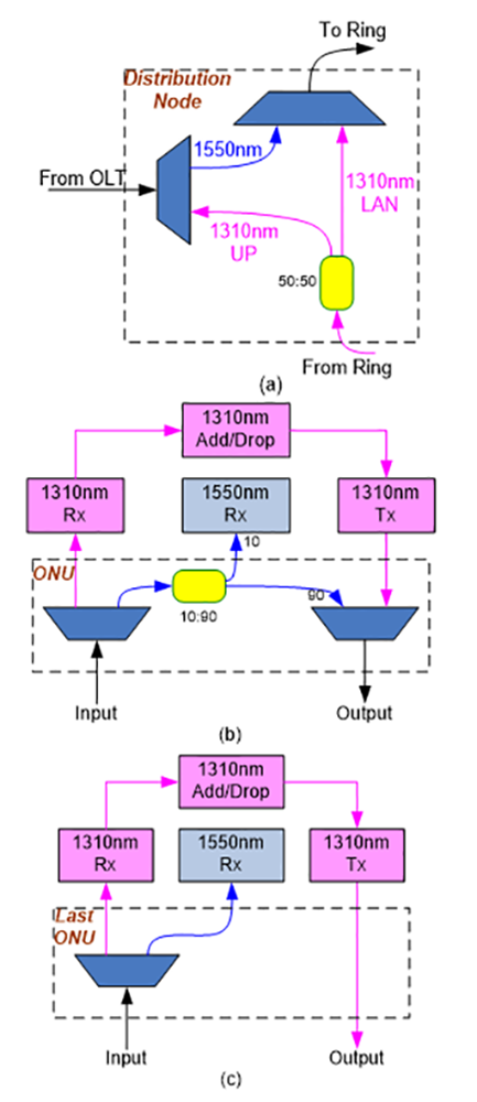
The ONUs are joined by point-to-point unidirectional links in a closed loop around the access ring. The US signal is transmitted sequentially, bit by bit, around the ring from one node to the next where it is terminated, processed, regenerated, and retransmitted at each node (ONU). In addition to the conventional transceiver maintained at each ONU (a λup US transmitter (Tx) and a λd DS receiver), this approach requires an extra receiver (Rx) tuned at λup to process the received US/LAN signal.
DS signal is coupled to the ring at port 2 of the optical circulator. After recombining it with the re-circulated US signal via the 2x1 CWDM combiner placed on the ring directly after the optical circulator, the combined signal then circulates around the ring (ONU1 through ONUN) in a Drop-and-Go fashion, where the DS signal is finally terminated at the last ONU. The US signal emerging from the last ONU is split into two replicas via the 20:80 1x2 passive splitter (Figures 2 & 3) placed on the ring directly after the last ONU. The first replica (80 %) is directed towards the OLT via circulator ports 1 and 3, where it is then received and processed by the US Rx (housed at the OLT), which accepts only MAN/WAN traffic, discards LAN traffic, and process the control messages, while the second replica (20 %) is allowed to recirculate around the ring after recombining with the DS signal via the 2x1 CWDM combiner.
At each ONU, the incoming combined signal is first separated into its two constituent: DS and US signals via the 1x2 CWDM DMUX housed at the ONU. Separated US signal is then received and processed via the US Rx housed at the ONU, where it is regenerated and retransmitted along with the ONU’s own local control and data traffic.
2.2. Protected State Architecture
The protected architecture as shown in Figure 3 is identical to that of the normal working architecture except for the following additional components: i) a redundant trunk fiber and distribution fiber ring; ii) a redundant transceiver pair located at the OLT; iii), Automatic Protection Switching (APS) module located at each ONU. The APS module attached to each ONU monitors the state of its adjacent distribution fiber paths and the state of the ONU and performs both fault detection and the APS functions. Each APS module houses a commercially available low loss 4x4 bidirectional Optical Switch (OS) that is capable of switching from any port to any port used for switching between working and protection fibers. It also includes two detection circuits comprised of a 1×2 CWDM filter (to separate the combined DS/US signal), a control circuit to configure the OS, and a p-i-n detector (except the first ONU (ONU1), which has two p-i-n detectors at the first detection circuit). The first detection circuit of each ONU (except the first ONU) is used to detect only the US signal via taping a small portion (about 1%) of the incoming combined (DS/US) signal and passing it through the CWDM filter. On the other hand, the first detection circuit of the first ONU is used to detect both US and DS signals. Likewise, the second detection circuit of each ONU is used to detect the outgoing US signal via taping a small portion (about 1%) of the outgoing combined signal.
2.3. Control Plane
This work utilizes the control and management messages defined by the IEEE 802.3ah multi-point control protocol (MPCP) standard [10] that facilitate the exchange of control and management information between the ONUs/SCs(Small Cells)/macro BS and OLT. The protocol relies on two Ethernet control messages, GATE (form OLT to ONUs) and REPORT (from ONUs to OLT and between ONUs/SCs/mBS) messages in its regular operation. Direct communication among ONUs/SCs/ mBS is achieved via the US wavelength channel {control messages along with both LAN and US data share the same US channel bandwidth (in-band signalling)}, which is terminated, processed, regenerated, and retransmitted at each ONU. Since control messages are processed and retransmitted at each node, the ONUs can directly communicate their US/LAN queue status and exchange signalling and control information with one another in a fully distributed fashion. Likewise, SCs/mBS can also directly communicate the status of their queues and radio resources and exchange signalling and control messages with one another. The control plane utilized among the ONUs/SCs/mBS can thus support a distributed HetNet RAN architecture, where each access node (ONU/SC/mBS) deployed around the ring has now a truly direct physical connectivity and is, thus, capable of directly communicating with all other access nodes, in conformity with LTE standards. Each access node maintains a database about the states of its own queue and every other ONU/mBS/SC’s queue on the ring. This information is updated each cycle whenever the ONU/ receives new REPORT messages from all other ONUs. During each cycle, the access nodes sequentially transmit their REPORT messages along with both US and LAN data in an ascending order within their granted timeslots around the ring from one node to the next, where each REPORT message is finally removed by the source ONU after making one trip around the ring. The REPORT message typically contains the desired size of the next timeslot based on the current ONU’s buffer occupancy. Note that the REPORT message contains the aggregate bandwidth of mobile data buffered at each SC’s queue (requested size of next timeslot). An identical Dynamic Bandwidth Allocation (DBA) module, which resides at each access node (ONU/SC/mBS), uses the REPORT messages during each cycle to calculate a new US timeslot assignment for each ONU. ONUs sequentially and independently run instances of the same DBA algorithm outputting identical bandwidth allocation results each cycle. The execution of the algorithm at each ONU starts immediately following the collection of all REPORT messages. Thus, all ONUs must execute the DBA algorithm prior to the expiration of the current cycle so that bandwidth allocations scheduled for the next cycle are guaranteed to be ready by the end of the current cycle. Once the algorithm is executed, the ONUs sequentially and orderly transmit their data without any collisions, eliminating the OLT's centralized task of processing requests and generating grants for bandwidth allocations. Thus, supported by the distributed control plane, most of the typical radio control functions including radio resource management, handover control, admission control, etc., can be independently implemented at each SC/mBS in a distributed approach without resorting to a central control entity.
3. Experimental Setup
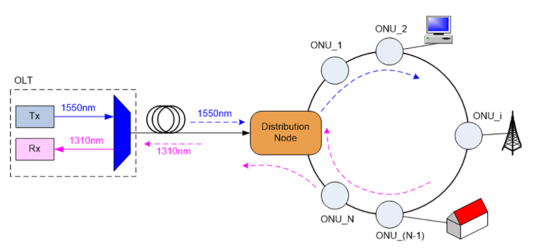
Figure 4 shows a typical structure of Ring PON. There is a Distribution Node (DN) connecting OLT and ONUs. Downstream signals enter DN and are then sent to the ring. It will be cut at last ONU after finishing transmitting a whole circle in the ring. Upstream signals are also transmitted in the ring. When it reaches last ONU, half of the signals will be sent to OLT and the other half will return to the ring to provide inter-communication in the ring. The inside structures of Distribution node and ONUs are shown in Figure 5 which have been slightly modified compared with those in [11].The experimental setup is shown in Figure 6. In this experiment, we measured the downstream transmission performance of a Ring PON at 10Gbps data rate and compared the results collected at 2.5Gbps as in Figure 8.
Since there is no 10:90 output coupler in last ONU (see Figure 5), the ONU before last will receive the lowest, and usually the worst, signals. The received power of the ONU before last is about 9~10dB smaller than that of last ONU, therefore the measurement of BER and eye diagram is conducted at the ONU before last.
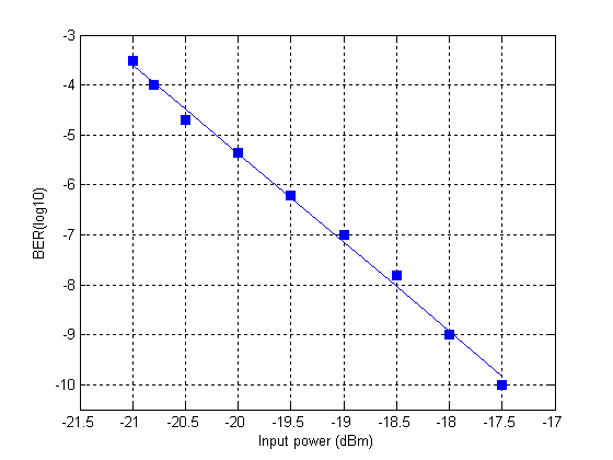
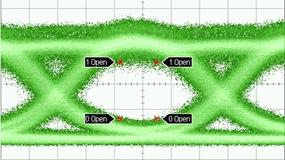
10Gbps PRBS signals from BERT (Agilent N4901B 13.5Gb/s serial BERT) were sent to RF driver to drive a MZ amplitude modulator (SDL 10Gb/s amplitude modulator). Then the modulated optical signals were amplified by EDFA, passed through a Variable Optical Attenuator (VOA) and finally reached the ring. The measured bit error rate and eye diagram at -17.5dBm received power are shown in Figure 7.
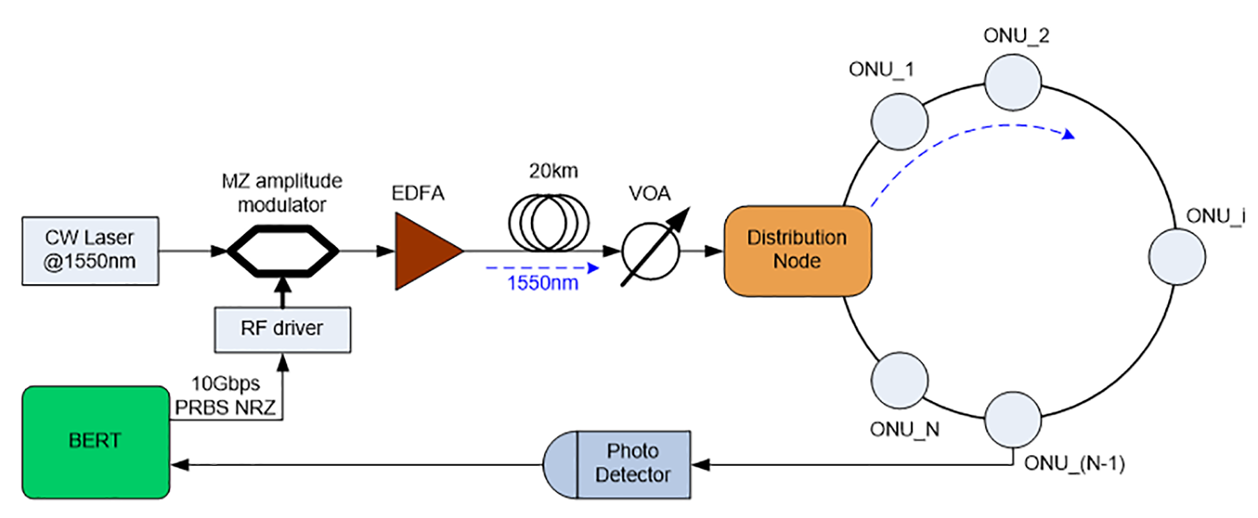
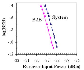
The experiment indicates that Ring PON still has a good downstream transmission performance under 10Gbps data rate. The transmission performance of upstream communication was not measured because downstream link will experience more insertion loss due to the existence of 10:90 output coupler compared with upstream link. There are 10 ONUs in the ring and the output power after EDFA is 7dBm.
Compared with the BER measurement of same structure at 2.5Gbps in Figure 8, the received power has to increase 9~11dB to provide same BER. The slope of the curves in Figure 8 are more steep than that in Figure 7, which might be attributed to the difference of signal source in two experiments.
The downstream transmission performance of Ring PON at 10Gbps data rate has been measured. We have proved that the signals have not been greatly degraded or distorted when Ring PON provides additional function to support inter-communication among ONUs in the ring. The comparison of BER of Ring PON at 10Gbps and 2.5Gbps has also been made. To guarantee same BER, the received power of Ring PON at 10Gbps has to be 9~11dB higher than that at 2.5Gbps.
4. Performance Evaluation
In this section, we first compare the performance of the proposed EPON-based mobile 5G RAN with that of the typically centralized 5G RAN. The performance metric used here is DS packet loss analysis as a function of US traffic load and average end-to end delay for a typical 5G and Ring-based 5G EPON network. We consider the practical case of non-uniform traffic load in which, during a given period, some BSs might be lightly loaded/idle, while other BSs might be heavily loaded. At a given total network load, different BSs have different average traffic loads. Under this non-uniform traffic load scenario, the significance of utilizing PON-based RAN architecture is established.
The following are the system parameters used for simulating the EPON-based RAN architecture: (1) a PON with 16 ONUs, each serving a varying number of BSs (a minimum of one BS to a maximum of 10 BSs), depending on the varying traffic load.; (2) aggregate access link data rate from the UEs to a given ONU is 100 Mb/s; (3) the RAN DS line rate (from the OLT/SGW(ePC) to the ONUs/BSs) is assumed to be same as the US line rate (from the ONUS/BSs to the OLT/SGW) and is equal to 10 Gb/s; (4) the average distance between the OLT/SGW(ePC) and ONS/BSs is 20 km; (5) the buffer size in each ONU/BS is 1 Mbyte; (6) the maximum EPON cycle time is 2 ms for US transmission, while a standard fixed periodic cycle of 10 ms is assumed for 5G US transmission (from the UEs to the BS); (7) the IEEE 802.3ah MPCP REPORT/GATE message is 64 bytes; (8) we assume that all network traffic is just mobile traffic initiated by 5G UEs, i.e., traditional EPON’s fixed wired end-user’s traffic is assumed to be zero; (9) the total mobile traffic is divided equally among US mobile traffic and local mobile LAN; (10) we assume that 5G/LTE GBR queues are mapped into EPON P0 queue and Non-GBR queues into P1 and P2 based on QoS parameters setting.; (12) the DBA scheme reported in [12] is used here to provision EPON US traffic, whereas the proportional fairness algorithm is used to provision 5G US traffic.
To have a fair comparison, all EPON-based RAN parameters listed above are also used for simulating the typical 5G except for the following: each and every dedicated link data rate of the typical 5G RAN in either US (16 dedicated point-to-point links between the ONUs/BSs and the OLT/SGW) or DS (16 dedicated point-to-point links between the OLT/SGW and the ONUs/BSs) direction is set to 625 Mbps. Thus, the aggregated link data rate in either direction is:
625 Mbps * 16 = 10 Gbps, which is equal to that of the EPON-based RAN.
4.1. Packet Loss Analysis and Average Delay of a typical 5G and Ring-based 5G EPON network
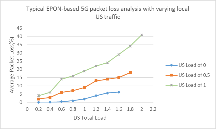
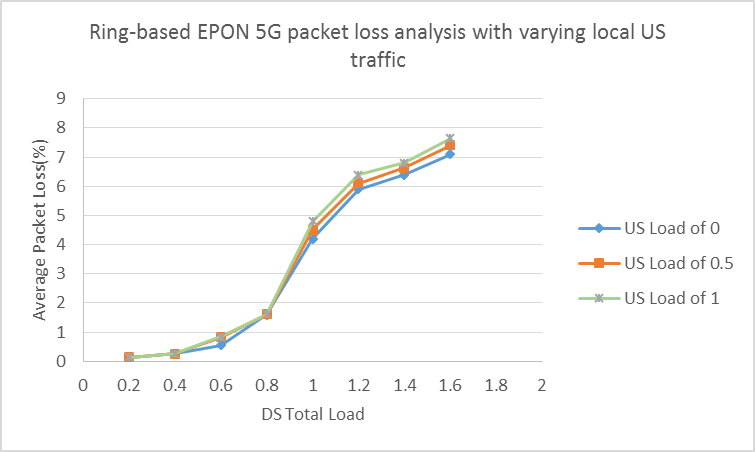
In this section, we compare the performance of our proposed EPON-based 5G network deployed in Ring architecture with EPON-based 5G deployed in typical tree configuration. The primary focus of analysis is the packet loss measurement as we vary the local US traffic load. Simulation model used here is same as described previously, however the typical 5G network in this case is also EPON-based meaning that BS’s of typical 5G network are integrated with ONU’s. Moreover simulation is performed in a way to see the effect of packet loss in the DS as a function of US local traffic. Simulation is run three times and results are averaged as shown in Figures 4 and 5.
As it is evident from Figures. 9 & 10, both ring and star EPON-5G networks have similar packet drop pattern when the US local traffic load is 0. However as the US local load is increased, EPON-based Ring network has similar packet loss pattern as when the US load was 0. On the other hand, this is not the case with typical star network where the packet loss increases exponentially when the local US traffic is increased as shown in Figure 4. The increase of packet drop in case of star network is attributed to the fact that the US traffic has to reach OLT from where it is transmitted as DS. Therefore, it obviously over-burdens the queues and US/DS resources. However, in the 5G-Ring network, the local US traffic is routed within the ring itself by the ONU’s and this not only off-loads the OLT but also saves precious network resources and hence increasing the local US traffic doesn’t affect the performance of the network. This is the key advantage of the proposed EPON-based 5G-Ring network.
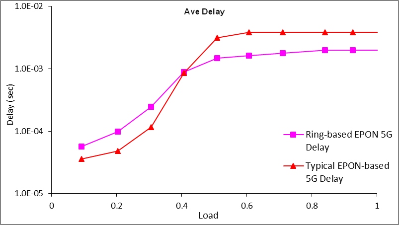
Finally, Figure 11 shows average end-to-end delay between typical EPON-based 5G versus ring-based EPON 5G. The result show that, at low load, typical 5G has less delay than the ring-based 5G but as the network load increases the proposed ring-based 5G shows better performance and less delay than the typical 5G network.
5. Conclusion
We have studied the performance analysis of a proposed distributed ring-based EPON 5G network vs. the typical EPON-based 5G network. The metrics used are packet loss analysis and average delay. The results show that the distributed ring-based EPON 5G shows superior performance, specifically as the more practical case when the network load increases. We also employed an experimental set-up of our proposed network to gather BER and eye-diagram at 10 Gbps. For future work we plan to convert our simulation program into an experimental set-up and test for higher data rates with power-budget analysis.
References
[1] S. O'Dea, “Smartphone users worldwide 2016-2023,” Available: View Article
[2] Sunny Bajaj, “The mobile workforce: the new movement,” Available: View Article
[3] Cisco Annual Internet Report (2018–2023) [Online]. Available: View Article
[4] UMTS Evolution, from 3GPP Release 7 to Release 8, HSPA and SAE/LTE, June 2008 UPDATE, www.3gamericans.org.
[5] 3GPP TS 23.401 “GPRS Enhancements for E-UTRAN access”, October 2007.
[6] H. Ekstrom, “QoS control in the 3GPP Evolved Packet system,” IEEE Communication Magazine, 47(2):76-83, 2009. View Article
[7] IEEE 802.6e-2005, “Air interface for fixed and mobile broadband wireless access systems.”
[8] 5G PPP Architecture Group, “View on 5G Architecture: https://5g-ppp.eu/wp-content/uploads/2019/07/5G-PPP-5G-Architecture-White-Paper_v3.0_PublicConsultation.pdf, June 2019. View Article
[9] S. R. Zaidi, Ajaz Sana and Shahab Hussain "An efficient & Cost-Effective EPON-Based Next Generation 5G Mobile Backhaul RAN Architecture," 2021 23rd International Conference on Advanced Communication Technology (ICACT), PyeongChang, Korea (South), pp. 248-253, 2021. View Article
[10] IEEE 802.3 Ethernet in the First Mile Study Group, http://www.ieee802.org/3/ efm/public/ index.html.
[11] H. Erkan, R. Zaidi, R. Dorsinville, and M. A. Ali, "A Simple and Cost Effective Ring-Based Local Access C/DWDM-PON Architecture for Supporting a Truly Shared LAN Capability," in Military Communications Conference, 2007. MILCOM 2007. IEEE, 2007), 1-8. View Article
[12] A. Delowar and M.A. Ali., “Ring-Based Local Access PON Architecture for Supporting Private Networking Capability,” OSA Journal of Optical Networking, 5(1):26-39, 2006. View Article